 info@kynix.com
 00852-6915 1330


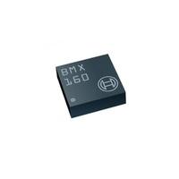
Have you ever struggled with noisy, unreliable motion data in your robotics or drone projects? Choosing the right Inertial Measurement Unit (IMU) is one of the most critical decisions you'll make. Enter the Bosch BMI088 sensor, a high-performance 6-axis IMU that has become a game-changer for applications demanding precision and stability, especially in high-vibration environments.This guide will walk you through everything you need to know about the BMI088. We'll dive deep into its core features, show you how to get it running with popular platforms like Arduino and Raspberry Pi, and compare it against its famous predecessor, the MPU6050. Whether you're a hobbyist just getting started or a seasoned engineer designing a cutting-edge system, this comprehensive overview will provide the insights you need to master the BMI088.[Insert Image: A high-resolution photo of the BMI088 sensor on a breakout board.] The Bosch BMI088 offers exceptional performance in a compact package.BMI088 Core Features and Technical SpecificationsUnderstanding the foundational capabilities of the BMI088 is key to leveraging its full potential. This sensor isn't just another IMU; it's a highly engineered solution for demanding applications. Let's break down what makes it stand out.What is the BMI088 and What Are Its Core Advantages?The Bosch BMI088 is a high-performance 6-axis Inertial Measurement Unit (IMU) that integrates a 16-bit triaxial accelerometer and a 16-bit triaxial gyroscope into a single, compact LGA package (3 x 4.5 x 0.95 mm³). It is specifically designed to provide extremely stable and low-noise sensor data, making it an ideal choice for applications like drones, robotics, and other systems that operate in challenging, high-vibration environments.Here are its primary advantages:Exceptional Vibration Robustness: This is arguably the BMI088's most significant selling point. It is mechanically designed to suppress vibrations, ensuring that the data you receive is clean and accurate, even when the sensor is mounted on a shaky drone frame or a fast-moving robot.Excellent Temperature Stability: The sensor exhibits a very low Temperature Coefficient of Offset (TCO), meaning its readings remain consistent across a wide range of operating temperatures (-40°C to 85°C). This is crucial for outdoor applications where environmental conditions can vary dramatically.High Performance & Precision: With 16-bit resolution for both the accelerometer and gyroscope, the BMI088 delivers the high-fidelity data needed for precise orientation tracking and motion detection.Wide Measurement Ranges: The accelerometer supports a g-range of up to ±24g, and the gyroscope can measure up to ±2000°/s, providing versatility for both subtle movements and high-dynamic maneuvers.Pro Tip: If your project involves any form of mechanical vibration (e.g., motors, propellers), the BMI088's unique design can save you countless hours of implementing complex software filters. Its hardware-level vibration damping is a significant advantage over many other IMUs.Deep Dive into the Official BMI088 DatasheetA sensor's datasheet is its bible. While datasheets can be dense, understanding the key parameters is essential for effective system design. Here’s a breakdown of the most critical specifications from the official BMI088 datasheet.SpecificationAccelerometerGyroscopeDigital Resolution16-bit16-bitMeasurement Range±3, ±6, ±12, ±24 g±125, ±250, ±500, ±1000, ±2000 °/sNoise Density230 µg/√Hz (at ±24g)<0.005 °/s/√HzZero-g Offset±20 mg (over lifetime)±1 °/s (over lifetime)TCO (Offset Drift)±0.2 mg/K±0.015 °/s/KInterfaceI²C (up to 400 kHz), SPI (up to 10 MHz)I²C (up to 400 kHz), SPI (up to 10 MHz)Important Note: The low TCO values are particularly impressive. A low TCO ensures that your sensor's 'zero' point doesn't drift significantly as the device heats up or cools down, which is critical for maintaining an accurate heading and orientation over time.Analyzing Gyroscope Noise and PerformanceFor any IMU, but especially for those used in drones and robotics, gyroscope noise is a critical performance metric. Low noise translates directly to smoother flight, more stable control loops, and more accurate orientation estimates. The BMI088 excels in this area.Its gyroscope was derived from Bosch's proven automotive technology, which is renowned for its stability and low drift. The sensor's low spectral noise and minimal drift are key differentiators, allowing developers to rely on its output with higher confidence. This reduces the burden on the sensor fusion algorithms (like a Kalman filter) that are typically used to process IMU data. This video provides an excellent comparison of different IMU gyros, highlighting the importance of low-noise hardware.About the Manufacturer: Bosch SensortecWhen you choose a BMI088, you're not just buying a component; you're investing in the expertise of Bosch Sensortec. As a global leader in MEMS (Micro-Electro-Mechanical Systems) sensors, Bosch has a long-standing reputation for quality, reliability, and innovation, particularly in the demanding automotive sector. This heritage is evident in the robust design and performance of the BMI088.BMI088 Integration and Development GuideGetting a new sensor up and running can sometimes be a hurdle. Fortunately, the BMI088 is well-supported across popular development platforms. This section provides practical guidance for integrating the BMI088 into your projects.Connecting and Programming with ArduinoArduino is the go-to platform for many makers and prototypers. Thanks to community-developed libraries, using the BMI088 with Arduino is straightforward.One of the most popular libraries is the Bolder Flight Systems BMI088 library. Here’s how you can get started:Installation: Download the library from GitHub and place it in your Arduino/libraries folder.Wiring: You can connect the sensor using either I²C or SPI.I²C Wiring: Connect VCC, GND, SDA (to A4 on Uno), and SCL (to A5 on Uno).SPI Wiring: Connect VCC, GND, SCK (to pin 13), MISO (to pin 12), MOSI (to pin 11), and the Chip Select (CS) pins to any available digital pins.Basic Code:#include "Bmi088.h"// I2C ExampleBmi088Accel accel(Wire, 0x18); // SDO1 is groundedBmi088Gyro gyro(Wire, 0x68); // SDO2 is groundedvoid setup() { Serial.begin(115200); while(!Serial) {} int status; status = accel.begin(); if (status < 0) { Serial.println("Accelerometer initialization failed!"); while(1); } status = gyro.begin(); if (status < 0) { Serial.println("Gyroscope initialization failed!"); while(1); }}void loop() { accel.readSensor(); gyro.readSensor(); Serial.print(accel.getAccelX_mss(), 4); Serial.print("\t"); Serial.print(gyro.getGyroX_rads(), 4); Serial.println(); delay(50);}[Insert Image: A clear wiring diagram showing an Arduino connected to a BMI088 breakout board via I2C.] A typical I²C wiring setup between an Arduino Uno and a BMI088 module.Driving the BMI088 on a Raspberry PiFor more complex projects requiring the power of a full-fledged computer, the Raspberry Pi is a popular choice. Interfacing the BMI088 with a Raspberry Pi is typically done using the I²C or SPI bus, and you can work with it using Python libraries like smbus2 or C/C++ libraries like wiringPi or the Linux kernel's IIO driver.The Linux kernel includes a built-in driver for the BMI088, which is the most robust method. You can enable it through the device tree overlays. Once enabled, the sensor data can be read directly from the filesystem under /sys/bus/iio/devices/.For a deeper dive into Linux drivers, check out the official kernel documentation.Porting and Application on the STM32 PlatformIn the world of professional and industrial embedded systems, STM32 microcontrollers are a dominant force. To use the BMI088 with STM32, you will typically communicate with the sensor using the HAL (Hardware Abstraction Layer) libraries for I²C or SPI. Bosch Sensortec provides a generic C driver that is not platform-specific. You will need to implement the bus communication (read/write) and delay functions for your specific STM32 target.Bosch's official driver can be found on their GitHub repository. The process generally involves:Integrating the Bosch Sensortec API into your STM32CubeIDE project.Implementing the user_spi_read, user_spi_write, user_i2c_read, user_i2c_write, and user_delay_ms functions using STM32 HAL calls.Initializing the sensor and reading data within your main application loop.How to Find and Use BMI088 Drivers & LibrariesFinding the right software is crucial. Here’s a quick guide to the best resources:Official Bosch Sensortec GitHub: The most reliable source for platform-agnostic C drivers. Find the BMI08x Sensor API here.Platform-Specific Libraries:Arduino: Search the Arduino Library Manager for "BMI088" or use the Bolder Flight Systems library.Raspberry Pi (Python): Look for community libraries on PyPI, though direct access via smbus2 or using the kernel driver is common.PX4/ArduPilot: These flight control stacks have built-in, highly optimized drivers for the BMI088.Vendor Examples: Manufacturers of breakout boards (like Adafruit, SparkFun, or Seeed Studio) often provide their own libraries and examples, which are excellent starting points. For example, check out Seeed Studio's Grove BMI088 Wiki.BMI088 Practical Application & CalibrationTheory is one thing, but real-world performance is what truly matters. This section covers how to get the most accurate data from your BMI088 through proper calibration and explores why it has become the go-to sensor for drone applications.The Ultimate Guide to Accurate BMI088 Sensor CalibrationDo you ever wonder why your robot drifts or your drone doesn't hold its position perfectly? The answer often lies in sensor calibration. No sensor is perfect out of the box; tiny manufacturing imperfections lead to offset and scaling errors. BMI088 calibration is the process of measuring these errors so you can correct for them in your software.For an IMU, this typically involves two main steps:Accelerometer Calibration: This corrects for zero-g offset (the reading when the axis is perfectly level) and scale factor errors. The most common method is the 6-point tumble calibration, where you place the sensor stationary on each of its six faces and record the readings. Since you know each stable face should measure exactly +1g or -1g on one axis and 0g on the others, you can calculate the necessary offsets and scaling factors.Gyroscope Calibration: This primarily corrects for zero-rate offset (the reading when the sensor is perfectly still). This is much simpler: just place the sensor on a stable, vibration-free surface and average its readings over several seconds. This average becomes the offset that you subtract from all future readings.Quote Block: "Calibration is not a one-time event. For high-precision applications, you should consider re-calibrating if the sensor is exposed to significant temperature changes or mechanical stress." - Embedded Systems TodayWhy is the BMI088 the Ideal Choice for Drones?The rise of high-performance FPV (First-Person View) drones and autonomous aerial vehicles has created a massive demand for better sensors. The BMI088 drone application is a perfect match for several reasons:Vibration Immunity: Drone motors and propellers create a high-frequency, high-amplitude vibration environment that can wreak havoc on IMU data. The BMI088's mechanical design inherently dampens these vibrations, providing a much cleaner signal to the flight controller. This means less reliance on software filtering, which in turn reduces latency and improves flight performance.Low Latency: The sensor's fast data output rates (up to 1600 Hz for the accelerometer) and SPI interface ensure that the flight controller receives fresh data with minimal delay, which is critical for responsive control.Temperature Stability: As drones fly, their internal electronics heat up. The BMI088's low temperature drift ensures that the drone's sense of 'level' doesn't change mid-flight, preventing unwanted drifting or instability.BMI088 Selection & Competitive ComparisonChoosing the right component involves not only understanding its features but also how it stacks up against alternatives and where to source it. This section provides a practical guide to selecting and purchasing the BMI088.BMI088 vs. MPU6050: A Head-to-Head Performance ShowdownFor years, the MPU6050 from InvenSense (now TDK) was the undisputed king of hobbyist IMUs. It was cheap, widely available, and good enough for many projects. However, technology has advanced, and the BMI088 vs. MPU6050 comparison clearly shows why the BMI088 is the superior choice for any new, performance-oriented design.Here is a direct comparison:FeatureBosch BMI088TDK InvenSense MPU6050Part StatusActiveNot for New Designs (Legacy)Vibration RobustnessExcellent, mechanically dampedStandardInterfaceI²C & SPI (up to 10 MHz)I²C only (up to 400 kHz)Gyro NoiseVery LowModerateTemperature StabilityExcellent (Low TCO)GoodAccelerometer RangeUp to ±24gUp to ±16gManufacturerBosch SensortecTDK InvenSenseThe Verdict: While the MPU6050 was a revolutionary sensor for its time, it is now considered obsolete for new designs. The BMI088 surpasses it in nearly every metric that matters for high-performance applications: lower noise, better temperature stability, superior vibration immunity, and a faster SPI interface option. For any new project involving drones, robotics, or other dynamic systems, the BMI088 is the clear winner.BMI088 Sensor Price Analysis and Purchasing ChannelsThe BMI088 price is highly competitive for the performance it offers. While slightly more expensive than older sensors like the MPU6050, the investment pays for itself in data quality and reliability. As of late 2025, single-unit pricing for the chip is typically in the $4 to $6 range, with significant discounts for bulk orders.Here are some of the most reliable places to purchase the BMI088:Major Distributors:Digi-KeyMouser ElectronicsArrow ElectronicsModule/Breakout Board Vendors:Seeed Studio (Grove)AdafruitSparkFunFor prototyping, purchasing a pre-made breakout board is highly recommended. These boards, like the Seeed Studio Grove - 6-Axis Accelerometer&Gyroscope(BMI088), typically cost between $15 and $30 and include the necessary voltage regulation and logic level shifting, making them easy to integrate with platforms like Arduino and Raspberry Pi.BMI088 Pinout and Circuit Design ReferenceUnderstanding the BMI088 pinout is essential for correct circuit design. The sensor comes in a 16-pin LGA package. Here is a simplified overview of the key pins:Pin NameI²C FunctionSPI FunctionDescriptionVDDPowerPowerMain power supply (1.71V to 3.6V)VDDIOPowerPowerDigital I/O power supply (1.2V to 3.6V)GNDGroundGroundGround connectionSCLI²C ClockSCKSerial ClockSDAI²C DataSDI (MOSI)Serial Data In (Master Out, Slave In)SDO1Address LSBSDO (MISO)Serial Data Out (Master In, Slave Out) / Accel Address SelectSDO2Address LSB-Gyro Address SelectCSB1-CS AccelChip Select for AccelerometerCSB2-CS GyroChip Select for GyroscopeINT1Interrupt 1Interrupt 1Accelerometer Interrupt PinINT2Interrupt 2Interrupt 2Gyroscope Interrupt Pin[Insert Image: A clear diagram of the BMI088 pinout.] The BMI088 pinout supports both I²C and 4-wire SPI communication protocols.When designing a circuit, ensure you place decoupling capacitors (typically 0.1µF and 1µF) close to the VDD and VDDIO pins to ensure a stable power supply. For I²C communication, remember to include pull-up resistors (e.g., 2.2kΩ to 10kΩ) on the SCL and SDA lines.Frequently Asked Questions (FAQ)Based on common questions from developers and engineers working with the BMI088, here are comprehensive answers to the most frequently asked questions:Interface and CommunicationWhat is the maximum clock frequency supported by the I²C interface of the BMI088?The maximum clock frequency supported by the I²C interface of the BMI088 is 400 kHz, as specified in the timing parameters. This is the standard "Fast Mode" I²C speed and provides a good balance between data throughput and signal integrity.What are the default I²C addresses for different parts of the BMI088?The default I²C addresses for different parts of the BMI088 are as follows:Accelerometer:SDO1 pin pulled to GND: 0x18 (0011000b)SDO1 pin pulled to VDDIO: 0x19 (0011001b)Gyroscope:SDO2 pin pulled to GND: 0x68 (1101000b)SDO2 pin pulled to VDDIO: 0x69 (1101001b)This addressing scheme allows you to have multiple BMI088 sensors on the same I²C bus by configuring the SDO pins differently.What are the key components of the I²C interface on the BMI088?The key components of the I²C interface on the BMI088 include:Communication Lines: SCL (Serial Clock) pin and SDA (Serial Data) pinBus Protocol: The I²C bus operates using master/slave communication, with the BMI088 acting as a slave deviceAddressing: The device supports 7-bit address mode only, with default addresses for accelerometer (0x18/0x19) and gyroscope (0x68/0x69)Timing Parameters: Clock frequency of 400 kHz, SCL low period of 1.3 μs, SCL high period of 0.6 μsConnectivity: External pull-up resistors (e.g., 1.2 kΩ) on SDO1 and SDO2 pins ensure proper signalingWhat are the timing specifications for the I²C interface of the BMI088?The BMI088 supports I²C communication with the following timing specifications:ParameterSymbolMin (μs)Max (μs)Clock FrequencyfSCL400400SCL Low PeriodtLOW1.31.3SCL High PeriodtHIGH0.60.6SDA Setup TimetSUDAT0.10.1SDA Hold TimetHDDAT00Setup Time for repeated StarttSUSTA0.60.6Hold Time for Start ConditiontHDSTA0.60.6Setup Time for Stop ConditiontSUSTO0.60.6Time before new TransmissiontBUF1.31.3Idle time (normal mode)tIDLE_wacc_nm22Idle time (suspend mode)tIDLE_wacc_sum10001000What are the two modes in the SPI interface of the BMI088 sensor?The two modes in the SPI interface of the BMI088 sensor are:00 Mode: CPOL (Clock Polarity) is set to '0' and CPHA (Clock Phase) is set to '0'11 Mode: CPOL is set to '1' and CPHA is set to '1'These modes are automatically selected based on the value of SCK after a falling edge of CSB.Can the BMI088 support simultaneous communication over both SPI and I²C interfaces?Yes, the BMI088 device supports operation over both SPI and I²C interfaces simultaneously. The interface selection is determined by Pin#07 (PS) 'protocol select' pin:PS = VDDIO selects the I²C protocolPS = GND selects the SPI protocolConstraints:Additional initialization steps are required for the accelerometer when using SPI protocolPins are shared between accelerometer and gyroscope, so different interfaces for each sensor are not advisableMechanical layout may cause pin sharing affecting certain applicationsWhat are the key differences between the SPI and I²C interfaces supported by the BMI088?The key differences include:Protocol Selection: Determined by Pin#07 (PS) state - VDDIO for I²C, GND for SPIInitialization Steps: SPI requires additional steps for accelerometer initializationPin Mapping: Detailed mapping varies between protocols for accelerometer and gyroscopeElectrical Specifications: Different pull-up resistance and input capacitance requirementsHardware and Physical SpecificationsWhat is the moisture sensitivity level of the BMI088 sensors?The moisture sensitivity level (MSL) of the BMI088 sensors corresponds to JEDEC Level 1, defined by IPC/JEDEC J-STD-020C and IPC/JEDEC J-STD-033A standards. The sensor can be used for lead-free soldering processes requiring peak temperatures up to 260°C during reflow. MSL Level 1 means indefinite storage in ambient conditions without special moisture protection.What are the tape and reel dimensions for BMI088?The tape and reel dimensions for BMI088 are:Reel Dimensions: L x W x H = 35cm x 35cm x 5cmTape Dimensions: A₀ = 4.85mm; B₀ = 3.35mm; K₀ = 1.20mmWhat is the standard cardboard box dimension for each reel of BMI088 devices?The standard cardboard box dimension for each reel of BMI088 devices is L x W x H = 35cm x 35cm x 5cm.What orientation does the BMI088 sensor have relative to the tape within the reel?The BMI088 sensor's orientation relative to the tape within the reel is specified in section 8.6.1 of the datasheet. For detailed information on orientation and dimensions, refer to the official datasheet section.Environmental and ComplianceWhat is the halogen-free status of the BMI088 sensor?The BMI088 sensor is halogen-free, meeting EC restriction of hazardous substances (RoHS) directive requirements (Directive 2011/65/EU of January 3rd, 2013). For detailed analysis results on halogen content, contact your Bosch Sensortec representative.What directive regulates the restriction of hazardous substances in the BMI088 sensor?The BMI088 sensor meets requirements of the EC restriction of hazardous substances (RoHS) directive, specifically Directive 2011/65/EU of the European Parliament and Council of January 3rd, 2013, which regulates restriction of certain hazardous substances in electrical and electronic equipment.Who can provide detailed analysis results on the halogen content of the BMI088?For detailed analysis results on the halogen content of the BMI088, contact your Bosch Sensortec representative. The sensor meets RoHS directive requirements and is confirmed halogen-free.Technical Performance and ConfigurationWhat is the purpose of the SDO1 pin in the BMI088?The SDO1 pin serves dual purposes:SPI Mode: Acts as data output for the accelerometer, transmitting digital acceleration signals to the host deviceI²C Mode: Functions as the least significant bit (LSB) of the I²C addressHow does the input capacitance affect the performance of the BMI088 in I²C mode?Input capacitance affects BMI088 performance in I²C mode by influencing signal integrity. Inadequate or excessive capacitance can cause slower communication speeds and increased noise. Optimal input capacitance values are crucial for stable, reliable I²C operation and proper timing between host device and sensor.What kind of buffer does BMI088 offer for sensor signals?BMI088 offers two integrated FIFO (First In, First Out) buffers for sensor signals from the accelerometer and gyroscope. These buffers help reduce or eliminate time-critical read access to the sensor, allowing high timing precision data acquisition.How are the new data ready interrupts mapped in the BMI088 device?New data ready interrupts in the BMI088 are mapped to interrupt pins INT1 and INT2. These can be configured through registers INT1_IO_CONF and INT2_IO_conf respectively, providing flexibility in electrical handling.What sensor health status information does the BMI088 provide through its self-test feature?The BMI088 provides sensor health status information through its self-test feature, including integrity checks of accelerometer and gyroscope circuits to ensure proper functionality.Advanced Configuration and TimingWhat impact do the ODR and OSR settings have on the 3dB cutoff frequency in BMI088?ODR (output data rate) and OSR (over-sampling ratio) settings significantly influence the 3dB cutoff frequency:ODR: Controls base sampling rate, directly impacting filter performanceOSR: Enhances sampling rate through multiplication, affecting cutoff frequency based on application requirementsSection 4.3.1 details specific ODR and OSR configurations showing how changes alter the 3dB cutoff frequency for optimized filtering performance.How are different ODR and low-pass filter bandwidth configurations handled in BMI088?The BMI088 integrates multiple configurable parameters through specific control registers. For the accelerometer, 3dB cutoff frequency is determined by selected ODR and over-sampling ratio (OSR) configured in the ACC_CONF register, with various combinations available from 12.5 Hz to 1600 Hz ODR.In what modes does the BMI088 operate regarding data synchronization timing?The BMI088 operates in two data synchronization timing modes:Normal mode: Minimum wait time of 2 μsSuspend mode: Minimum wait time of 1000 μsThis ensures proper internal data synchronization during different operational states.What is the minimum wait time required for data synchronization in the BMI088 device?The minimum wait time required for data synchronization is 2 μs in normal mode or 1000 μs in suspend mode.SPI Interface DetailsHow does the tSDO_OD parameter affect the accuracy of the BMI088 measurements?The tSDO_OD parameter defines SPI data line output delay. Longer tSDO_OD increases time between master device byte transmission and sensor response, potentially introducing latencies. Proper tSDO_OD configuration is crucial for maintaining measurement accuracy and correct data processing without loss.What conditions are required for achieving the minimum clock frequency of 10 MHz in the BMI088 sensor?To achieve 10 MHz clock frequency:Configure SPI interface for nominal maximum frequency operationProvide stable power supply meeting voltage and current specificationsEnsure proper capacitive loading on SDI and SDO pins for signal integrityMaster device must generate accurate 10 MHz SPI clock signals with proper setup/hold timesProperly initialize BMI088 in SPI mode following Section 6.1 proceduresWhat is meant by 'tCSB_setup' and 'tCSB_hold' in the BMI088 sensor context?These terms refer to SPI interface timing parameters:tCSB_setup: Time for Chip Select Buffer (CSB) to transition from setup to stable state after falling edge on CSB1 pintCSB_hold: Duration CSB remains in hold state after rising edge, preventing other devices from communicating during this periodThese parameters ensure proper SPI bus communication and correct accelerometer operation.Conclusion: Mastering the BMI088 for Next-Generation ProjectsThe Bosch BMI088 sensor represents a significant leap forward in IMU technology, particularly for applications that demand high performance in challenging environments. Throughout this comprehensive guide, we've explored its exceptional vibration robustness, superior temperature stability, and versatile integration options across popular development platforms.Key takeaways from our deep dive include the BMI088's clear advantages over legacy sensors like the MPU6050, its straightforward integration with Arduino and Raspberry Pi platforms, and its critical role in enabling the next generation of autonomous drones and robotics systems. The sensor's hardware-level vibration damping, combined with its low-noise gyroscope derived from automotive-grade technology, makes it an ideal choice for any motion-sensing application where precision matters.As we look toward the future of embedded systems and autonomous vehicles, sensors like the BMI088 will continue to play a pivotal role in enabling more sophisticated and reliable motion detection. Whether you're building your first drone, developing an industrial robot, or creating the next breakthrough in wearable technology, the BMI088 provides the foundation for accurate, stable motion sensing that you can depend on.The investment in a high-quality IMU like the BMI088 pays dividends in reduced development time, improved system performance, and enhanced user experience. As sensor technology continues to evolve, Bosch Sensortec's commitment to innovation ensures that the BMI088 will remain a relevant and powerful choice for years to come.Extended ReadingFor those interested in diving deeper into related topics, consider exploring these areas:Advanced Sensor Fusion Algorithms: Learn how to combine IMU data with other sensors for enhanced accuracyKalman Filter Implementation: Understand how to process noisy sensor data for optimal state estimationDrone Flight Controller Design: Explore how IMUs integrate into complete autonomous flight systemsIndustrial Robotics Applications: Discover how high-performance IMUs enable precise robotic controlReferences[1] Bosch Sensortec. "BMI088 Datasheet." BST-BMI088-DS001. https://www.bosch-sensortec.com/media/boschsensortec/downloads/datasheets/bst-bmi088-ds001.pdf[2] Bosch Sensortec. "Inertial Measurement Unit BMI088." Product Page. https://www.bosch-sensortec.com/products/motion-sensors/imus/bmi088/[3] Bolder Flight Systems. "BMI088 Arduino Library." GitHub Repository. https://github.com/bolderflight/bmi088-arduino[4] Arduino Documentation. "Bolder Flight Systems BMI088." Arduino Libraries. https://docs.arduino.cc/libraries/bolder-flight-systems-bmi088/[5] NVIDIA Corporation. "BMI088 IMU Driver." Jetson Linux Developer Guide. https://docs.nvidia.com/jetson/archives/r36.4.3/DeveloperGuide/SD/Kernel/Bmi088ImuIioDriver.html[6] Seeed Studio. "Grove - 6-Axis Accelerometer&Gyroscope(BMI088)." Wiki Documentation. https://wiki.seeedstudio.com/Grove-6-Axis_Accelerometer&Gyroscope_BMI088/[7] Digi-Key Electronics. "BMI088 Product Details." Component Distributor. https://www.digikey.com/en/products/detail/bosch-sensortec/BMI088/8634936[8] Mouser Electronics. "BMI088 Specifications." Electronic Components. https://www.mouser.com/ProductDetail/Bosch-Sensortec/BMI088[9] Arrow Electronics. "Bosch's High Performance IMU: BMI088." Technical Article. https://www.arrow.com/en/research-and-events/articles/bosch-bmi088-high-performance-inertial-measurement-unit[10] Utmel. "BMI088 vs MPU-6050 Comparison." Component Comparison. https://www.utmel.com/compare/BMI088--6195080-vs-MPU-6050--6195061[11] Bosch Sensortec. "BMI08x Sensor API." GitHub Repository. https://github.com/BoschSensortec/BMI08x-Sensor-API[12] Linux Kernel Documentation. "Industrial I/O Subsystem." Kernel Documentation. https://www.kernel.org/doc/html/latest/iio/index.html
On 2025-09-25
![ENC624J600-I/PT microcontroller: Datasheet, Features, Application[FAQ]](https://static.kynix.com/imgs/BlogImage-v/20230316173617653713.jpg)
![ATMEGA1280-16AU microcontroller: Datasheet, Features, Application[FAQ]](https://static.kynix.com/imgs/BlogImage-v/20230309165108141686.png)
![STM8S207CBT6 Microcontroller: Datasheet, Features, Application[FAQ]](https://static.kynix.com/imgs/BlogImage-v/20230309165213605373.png)
![2N7002P Mosfet: Datasheet, Pinout, Features [FAQ]](https://static.kynix.com/imgs/BlogImage-v/ky_bg_head_20211021173017.jpg)
![L298N Motor Driver: Datasheet, Arduino, Circuit [Video&FAQ]](https://static.kynix.com/imgs/BlogImage-v/ky_bg_head_20211021154504.jpg)
![MCP2515-I/P CAN Controller: CAD Models, Datasheet, Features [Video&FAQ]](https://static.kynix.com/imgs/BlogImage-v/ky_bg_head_20211021153456.jpg)


