 info@kynix.com
 00852-6915 1330


 0
0


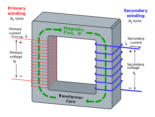

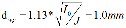
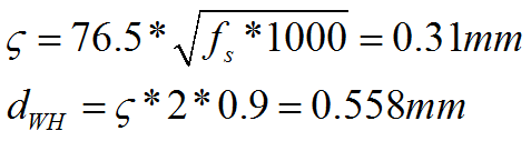
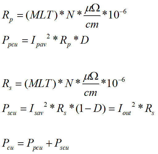
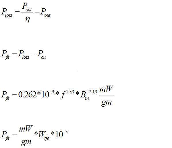

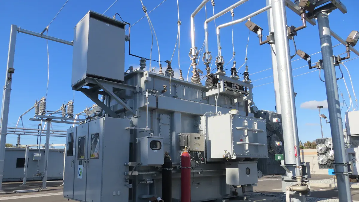
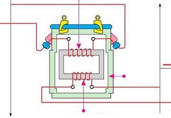
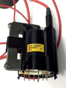
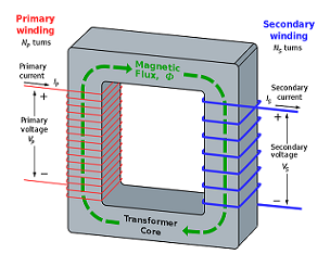
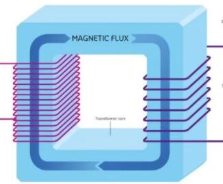
Power transformers are essential devices that adjust voltage levels to efficiently transfer electricity across long distances. They work by using electromagnetic induction to convert high voltage from power plants into lower voltage suitable for homes and businesses. Imagine them as bridges that connect different parts of the electrical system, ensuring smooth energy flow. Without reliable transformers, power outages and energy losses could disrupt daily life. In fact, transformer failures account for over 33% of prolonged outages, emphasizing their critical role in maintaining stable electricity supply.Power Transformers OverviewWhat Are Power TransformersPower transformers are static devices that transfer electrical energy between two or more circuits without changing the frequency. These devices use electromagnetic induction to move energy from one coil, called the primary winding, to another coil, called the secondary winding. The main purpose of power transformers is to change voltage levels, making it possible to send electricity over long distances and deliver it safely to homes and businesses.Electrical transformers do not create or use energy. They only transfer it from one place to another. This makes them passive devices in the power system.The basics of transformer operation rely on the turns ratio between the primary and secondary windings. When the number of turns in the coils changes, the voltage changes as well. This process allows transformers to step voltage up or down as needed. The magnetic core inside the transformer links the windings and helps induce voltage changes when current flows through the primary coil.Electrical transformers are essential for power generation, transmission, and distribution.They provide galvanic isolation, which means they separate different parts of the electrical system for safety.Transformers help match impedance and supply multiple voltage levels for different uses.Researchers have studied transformer basics to improve performance and safety. For example:Canola oil and other vegetable oils have been tested as eco-friendly insulating fluids for high-voltage transformers. These oils show good fire safety and stability at high temperatures.Some studies found that adding antioxidants to mineral oil and vegetable oil blends can improve insulation performance.New testing methods, like using ultrasound and artificial intelligence, help monitor transformer oil quality and predict faults.These research efforts support the development of safer and more sustainable electrical transformers for modern power systems.Role in Electrical SystemsTransformers play a vital role in every stage of the electrical grid. They step up voltage at power plants so electricity can travel long distances with less energy loss. When electricity reaches cities and neighborhoods, other transformers step the voltage down to safe levels for homes and businesses.Electrical transformers also help keep the power system reliable. Operators use advanced transformer infrastructure to collect real-time data from transformers. This data helps them spot overloaded or underused transformers and manage the system more effectively. By monitoring transformer basics, operators can prevent failures and reduce the risk of power outages.A study using survival analysis showed that spending more on preventive maintenance for power transformers lowers failure rates and outage costs. This means regular care and monitoring of transformers can keep the electrical system running smoothly, even in high-demand situations.Modern electrical transformers use advanced diagnostic tools, such as machine learning and big data analysis, to detect faults early. These tools help predict when a transformer might fail, allowing for timely repairs and better asset management.Electrical transformers support renewable energy systems, like wind farms, by handling unique stresses and helping detect faults.Sensor arrays and pattern recognition methods can analyze gases in transformer oil, giving early warnings of problems.These technologies make transformers more efficient and reliable, which is crucial for delivering electricity safely and consistently.Operating Principle of Power TransformersElectromagnetic InductionThe operating principle of power transformers centers on electromagnetic induction. This process allows transformers to transfer electrical energy from one coil to another without direct contact. When an alternating current flows through the primary coil, it creates a changing magnetic field. This magnetic field passes through the core and reaches the secondary coil. The changing magnetic field in the core induces a voltage in the secondary coil. This is the heart of transformer basics.A simple analogy helps explain this process. Imagine two people standing on either side of a fence. One person waves a magnet back and forth. The other person holds a coil of wire near the fence. The moving magnet creates a changing magnetic field, which passes through the fence and causes electricity to flow in the coil. In transformers, the core acts like the fence, guiding the magnetic field from one coil to the other.Most transformers achieve high efficiency in this process. Scientific experiments, such as heat run tests and computational fluid dynamics simulations, confirm that transformers can transfer about 99% of the input power to the output. Only about 1% is lost as heat, which is known as transformer losses. These experiments also show that the temperature inside a transformer changes with the load. The thermal time constant, which measures how fast the transformer heats up, depends on the amount of current flowing. This helps engineers design transformers that stay safe and reliable, even during overloads.The efficiency of electromagnetic induction in transformers depends on several factors. The core material, the number of turns in each coil, and the frequency of the alternating current all play a role. The equation for induced voltage is e = -N dφ/dt, where N is the number of turns and dφ/dt is the rate of change of magnetic flux. This equation shows how transformer basics rely on the relationship between the coils and the magnetic field.Note: Electromagnetic induction allows transformers to change voltage levels without changing the frequency of the electricity. This makes them ideal for power grids, where frequency must stay constant.Voltage TransformationVoltage transformation is the main function of power transformers. The operating principle of power transformers uses the turns ratio between the primary and secondary coils to change voltage levels. If the secondary coil has more turns than the primary, the transformer increases the voltage. If it has fewer turns, the transformer decreases the voltage. This process is called voltage conversion.The relationship between the number of turns and the voltage is simple. The ratio of the secondary turns to the primary turns equals the ratio of the output voltage to the input voltage. For example, if a transformer has 200 turns on the primary coil and 25 turns on the secondary coil, it can change 120 volts on the input side to 15 volts on the output side. This is a key part of transformer basics.Transformers do not change the frequency of the electricity. They only change the voltage. This feature is important for the stability of the electrical system. The operating principle of power transformers ensures that the power delivered to homes and businesses matches what is needed for safe operation.A table can help summarize the relationship between coil turns and voltage:Primary Turns (Np)Secondary Turns (Ns)Input Voltage (Vp)Output Voltage (Vs)20025120 V15 V100200110 V220 VTransformer losses, such as heat, occur mainly in the core and windings. However, these losses are small compared to the total power transferred. Most transformers operate at about 99% efficiency, making them very effective for voltage transformation in power systems.Tip: The ability to change voltage levels safely and efficiently makes transformers a key part of modern electrical networks.Components of Power TransformersImage Source: unsplashCore and WindingsThe core and windings form the heart of any transformer. The core consists of thin laminated steel sheets, each less than 1 mm thick, with a carbon content below 0.1%. Engineers add silicon to the steel to reduce energy losses from eddy currents. The core has two main parts: limbs, which hold the windings, and yokes, which connect the limbs at the top and bottom. This structure helps guide the magnetic field efficiently.Windings are made from copper or aluminum wire. The number of turns in each winding determines the voltage transformation. High-voltage windings use more turns of thinner wire, while low-voltage windings use fewer turns of thicker wire. Insulation materials, such as electrical-grade paper and transformer oil, protect the windings and prevent short circuits. All copper and aluminum transformers must meet strict DOE efficiency standards. These standards ensure that the components of power transformers operate with minimal energy loss.ComponentSpecification / Measurement DetailsCoreLaminated steel sheets < 1 mm thick; carbon < 0.1%; silicon alloyingCore StructureLimbs (vertical), Yokes (horizontal)WindingsCopper or aluminum; HV: more turns, thinner wire; LV: fewer turns, thicker wireInsulationElectrical-grade paper, pressboard, transformer oilCooling MethodsONAN (Oil Natural Air Natural), ONAF (Oil Natural Air Forced)Note: Transformer design programs adjust to meet national and international standards, such as IEC and IEEE, to guarantee reliable performance.Primary and Secondary CoilsThe primary coil receives the input voltage, while the secondary coil delivers the output voltage. The ratio of turns between these coils sets the voltage transformation. Engineers optimize coil design to reduce energy losses, such as copper losses (I2R) and iron losses. They select the wire gauge and coil shape carefully to balance efficiency and cost.Researchers use advanced algorithms to find the best design for both coils. They consider scenarios like minimizing copper use in the primary or secondary coil, or finding a compromise between the two. This approach helps create efficient and reliable components of power transformers for every application.Three-phase transformers use star (Y) or delta (Δ) winding configurations.Cooling methods, such as ONAN and ONAF, keep the coils at safe temperatures.The transformer equation, Vs = (Vp / Np) × Ns, links voltage to the number of coil turns.Types of Power TransformersImage Source: pexelsStep-Up and Step-Down TransformersEngineers use two main types of power transformers to manage voltage: the step-up transformer and the step-down transformer. A step-up transformer increases voltage from the primary to the secondary coil. This type is essential for power transmission over long distances because higher voltage reduces energy loss. A step-down transformer does the opposite. It lowers voltage to safe levels for homes and businesses. Both types play a key role in the electrical grid.The table below compares the main features of step-up and step-down transformers:AspectStep-Up TransformerStep-Down TransformerTurns RatioSecondary has more turns than primary (Ns > Np)Secondary has fewer turns than primary (Ns < Np)Voltage EffectIncreases output voltageDecreases output voltageCurrent EffectDecreases output currentIncreases output currentMaintenanceRequires less maintenanceRequires more maintenanceApplicationsPower transmission, X-ray machinesHomes, offices, power adaptersEfficiencyAbout 98%About 98%A step up transformer is often found at power plants. It prepares electricity for high-voltage transmission lines. A step down transformer is common in neighborhoods and buildings, making electricity safe for everyday use.Distribution and Transmission TransformersDistribution and transmission transformers serve different roles in the power grid. Transmission transformers handle high-voltage transmission, moving electricity from power plants to substations across long distances. Distribution transformers lower the voltage again, making it usable for homes, schools, and businesses.Real-world data shows the importance of these types of power transformers. Transmission and distribution transformers each account for over 40% of the global installed transformer capacity. Power grids worldwide use about 4.7 million kilometers of transmission circuits and up to 104 million kilometers of distribution lines. Utilities rely on real-time data from distribution transformers to manage changing power flows and keep the grid stable.Market research groups power transformers by voltage level, application, phase, insulation, core type, and rating. The table below shows these categories:CategorySubcategories / TypesUsage and Performance ContextVoltage LevelLow Voltage, Medium Voltage, High VoltageResidential (low), industrial (medium), transmission (high)ApplicationResidential, Commercial, IndustrialHomes, businesses, heavy industryPhaseSingle Phase, Three PhaseThree-phase for industry and large-scale useInsulationOil, Solid, Gas, AirImpacts safety and performanceCore TypeShell, Closed, BerryAffects cooling and efficiencyRating (MVA)100-500, 501-800, 801-1200Linked to industrial and utility needsImage Source: statics.mylandingpages.coMedium voltage transformers hold the largest revenue share in 2024. Industrial applications lead in growth, while high-voltage transformers are expected to grow fastest in the coming years.Tip: Choosing the right type of power transformer ensures safe, efficient, and reliable electricity for everyone.Applications of TransformersPower DistributionElectrical transformers play a central role in power distribution systems around the world. Cities and towns rely on these devices to deliver electricity safely and efficiently. In urban areas, substation transformers help manage the flow of electricity through complex networks. For example, studies in China have shown that transformer capacity can limit how much electricity a city can supply. When a transformer reaches its limit, it becomes a bottleneck for the entire network. Utility companies use these findings to decide when to upgrade transformers and improve network security.In the United States, the scale of power distribution is massive. There are between 60 and 80 million distribution transformers in use as of late 2024. These electrical transformers help move electricity from transmission lines to homes and businesses. The demand for transformers is rising quickly. By 2050, experts expect the need for transformer capacity to grow by up to 260% compared to 2021. Many transformers in use today are over 40 years old, which means utilities must plan for replacements and upgrades. Supply chain issues and long manufacturing times add to the challenge.Note: Distribution transformers in the U.S. lose nearly 2% of all electricity generated, mostly due to core losses at low loads. Improving efficiency could save billions of dollars over time.Efficiency and ReliabilityEfficiency and reliability are key factors in the performance of electrical transformers. In industrial settings, high-efficiency power transformers help companies save money and reduce their impact on the environment. The table below shows how different types of transformers perform:Transformer TypeEfficiency RangeMaximum Load Resistance (Ω)General Market Transformers95% – 98.5%300High-Power TransformersUp to 99.7%N/AStep-Down TransformersNot specified80Most electrical transformers in industry operate between 95% and 99% efficiency. Regular maintenance and balanced loading help keep these numbers high. Tools like Distribution Transformer Monitoring Units allow operators to check transformer health in real time. Power Factor Correction methods, both passive and active, also improve efficiency and voltage stability.Reliability matters because transformers support critical infrastructure. When a transformer fails, it can cause power outages and disrupt daily life. Utilities monitor transformer performance and replace aging units to keep the grid stable. As more renewable energy sources and electric vehicles connect to the grid, the need for reliable and efficient electrical transformers will only increase.Power transformers keep electricity flowing safely and reliably in homes and businesses. Statistical models, such as the Weibull distribution, help experts predict transformer lifespan and plan maintenance. Studies show that insulation issues and overloads cause most failures, which highlights the need for regular checks. Researchers use advanced simulations and experiments to improve transformer design and performance. These efforts help everyone enjoy stable power every day. For those interested, exploring recent research on transformer reliability and thermal modeling can offer deeper insights.FAQWhat is the main job of a power transformer?A power transformer changes voltage levels to move electricity safely and efficiently. It helps send power over long distances and delivers the right voltage to homes and businesses.Why do transformers need cooling?Transformers heat up during use. Cooling systems, like oil or fans, keep the temperature safe. This prevents damage and helps the transformer last longer.Can a transformer work with direct current (DC)?No, a transformer only works with alternating current (AC). The process of electromagnetic induction needs a changing magnetic field, which DC does not provide.How do people know if a transformer is failing?Operators use sensors and monitoring tools.They check for unusual sounds, heat, or oil leaks.Early signs help prevent bigger problems.
On 2025-07-18


