info@kynix.com
 00852-6915 1330


 0



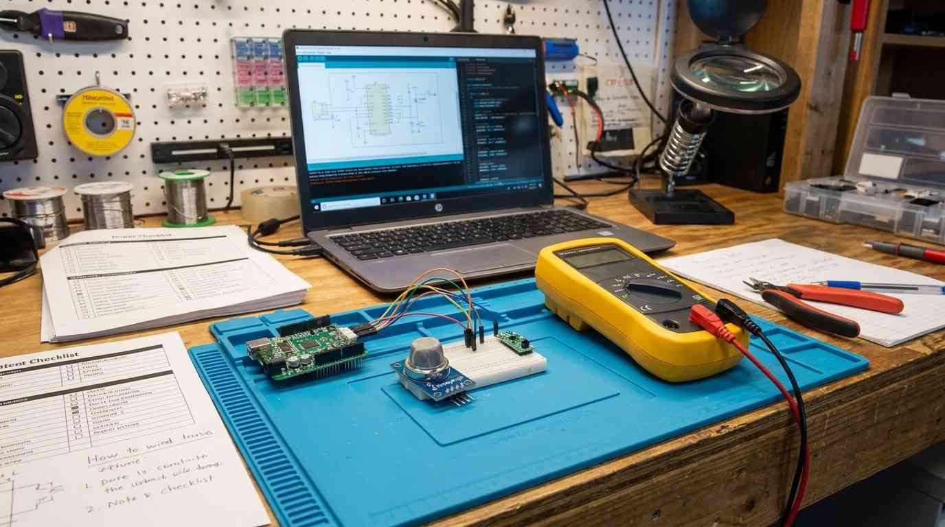
The short answer: there is no universal gas sensor for IoT. Gas sensor selection is a coupled engineering trade-off between sensing physics, power budget, temperature/humidity stability, response time, measurement selectivity, and field replacement cost.As a practical starting point for gas sensor IoT selection:Battery-powered toxic gas detection for CO, H₂S, NO₂, or O₂ usually points to electrochemical sensors operating at microampere-level signals.Long-life CO₂ or methane measurement with stable baselines usually points to non-dispersive infrared (NDIR) sensors.Broad indoor air quality, total VOC trend, or smoke screening usually points to metal-oxide semiconductor (MOS/MOX) sensors with duty-cycled micro-hotplates.Flammable gas detection across 0–100% LEL usually points to catalytic bead pellistors or infrared sensors on mains/industrial power rails.The rest of this guide breaks down why those choices hold, where they fail, and what to verify before finalizing a design.1. The 5-vector IoT gas sensing decision frameworkBefore selecting a part number, predefine five system vectors. Most failed gas-sensor designs come from fixing one vector and ignoring the others.Decision vectorWhat to freeze earlyWhy it changes the architectureTarget gas and measurement envelopeSpecific gas, concentration range, resolution, detection limitDetermines whether redox, infrared absorption, or chemiresistive physics is appropriatePower and energy sourceMains, LiSOCl₂, Li-ion, energy harvesting, peak-pulse capabilityRules out continuous heater devices or requires aggressive duty cyclingEnvironmental profileTemperature, humidity, dust, water spray, interfering gasesDrives enclosure design, filters, compensation, and sensor lifetimeDynamic performance and lifespanRequired T90, warm-up time, acceptable drift, service intervalSeparates consumable electrochemical cells from long-life optical or solid-state optionsInterface and total cost of ownershipRaw analog vs. digital module, field replacement strategy, calibration accessChanges analog front-end, firmware, PCB layout, and service architectureA useful decision order for embedded teams:Identify the gas. Is it toxic, flammable, infrared-active, or broad VOC?Define the power envelope. Can the node deliver hundreds of milliwatts, or only microamps?Decide whether the output must be absolute concentration. For safety compliance or ppm-level controls, avoid broad MOS as the sole signal.Assess environment extremes. High humidity, condensing atmospheres, and low oxygen environments directly remove some technologies.Model total service cost. A sensor that must be replaced every two years should be field-swappable.2. Sensor Topologies Compared: Physics, Performance Matrices, and Application BoundariesThe main IoT-relevant sensor classes are electrochemical, NDIR, MOS/MOX, and catalytic bead pellistors. They do not compete directly; each occupies a different physical and application boundary.Sensing technologyPrimary physical principleTypical target gasesPower consumptionResponse timeSelectivity and cross-sensitivitiesOperating lifespanRelative BOM cost tierElectrochemical (EC)Redox reaction at electrodes produces proportional currentCO, H₂S, NO₂, O₂, SO₂Sub-mW continuous; nanoampere-to-microampere signal outputSeconds to minutes, depending on filter, electrolyte, and temperatureHigh for target gas; cross-sensitivity to hydrogen, some VOCs1–3 years typical; 12–18 months for reactive acid gasesMediumNDIRGas absorbs infrared light at specific wavelengths; concentration derived from Beer-Lambert lawCO₂, CH₄, infrared-active hydrocarbonsLow average power via pulsed IR source; high peak supply currentTens of seconds to minutes depending on chamber volumeHigh for infrared-active gas; immune to catalytic poisoning5–10+ years typicalHighMOS/MOXHeated metal-oxide film changes resistance during gas adsorptionBroad VOCs, smoke, combustible gas indicationHigh continuous heater power; low average power with MEMS duty cyclingFast with MEMS micro-hotplates; slower with ceramic heatersLow; responds broadly to VOCs, humidity, and temperatureModerate; can be poisoned by silicones and heavy solventsLow to mediumCatalytic bead / pellistorCatalytic oxidation on heated bead changes bridge resistanceFlammable gases, 0–100% LEL140 mW to 190+ mW per bead pair continuousFast, typically secondsBroad combustible response; requires oxygen2–3 years typicalLow to mediumGas Sensor Technology Comparison: Physics and PowerElectrochemical sensors: microampere toxic gas detectionElectrochemical gas sensors are the closest fit for battery-operated single-gas toxic monitoring. The target gas diffuses through a barrier into a liquid or gel electrolyte and reacts at the working electrode. The resulting redox current is proportional to gas concentration.For industrial toxic cells, output signals are typically in the nanoampere-to-microampere range. For example, Alphasense CO, H₂S, and O₂ amperometric cells generate linear current outputs, with oxygen cells often producing roughly 80–120 μA in air and zero-baseline currents below 2.5 μA at 20°C. That current must be conditioned by a high-impedance transimpedance amplifier before the MCU ADC.Best for: battery-powered CO, H₂S, NO₂, and O₂ monitoring.Main weaknesses: limited consumable lifespan, sensitivity to extreme humidity, temperature-dependent output, and the need for periodic recalibration.Do not choose EC when: the deployment is a permanently sealed, zero-maintenance outdoor device; when the gas is primarily a broad VOC mixture; or when the environment exceeds the cell's rated humidity or temperature envelope.NDIR sensors: drift-resistant optical measurementNDIR sensors operate by pulsing an infrared source through an optical chamber and filtering for a narrow absorption wavelength. CO₂ absorbs near 4.26 μm, while methane and many hydrocarbons absorb in the 3.3–3.4 μm region. The gas reduces detected optical intensity; concentration is calculated from that attenuation.NDIR is highly selective for infrared-active gases and is not subject to the same chemical poisoning mechanisms as pellistors or MOS sensors. However, homonuclear diatomic molecules such as O₂, N₂, and H₂ do not absorb infrared light in the same useful way and cannot be measured with standard NDIR. These fundamental optical principles are well documented in technical comparisons of NDIR vs electrochemical gas sensors[8].Best for: indoor CO₂ monitoring, greenhouse CH₄ measurement, ventilation control, and long-life environmental nodes.Main weaknesses: higher device cost, larger optical path, peak-current demand during emitter pulses, and condensation risk in humid chambers.Do not choose NDIR when: measuring oxygen depletion, hydrogen leaks, or non-infrared-active gases, or when the BOM cannot support an optical cell.MOS/MOX sensors: high-sensitivity chemiresistorsMOS sensors rely on a heated polycrystalline metal-oxide layer, often tin oxide or tungsten oxide. Gas adsorption changes the grain-boundary resistance. The device is typically heated to 200°C–400°C.MOS is attractive because it is small, low cost, and extremely sensitive to many VOCs. But it is not a precise single-gas analyzer. Humidity changes, temperature swings, and common household VOCs can produce large baseline changes.A useful example is the Bosch BME688 MEMS gas sensor. In its standard gas-scan mode, it draws about 3.9 mA, drops to 0.9 mA in low-power mode, and falls to roughly 90 μA in ultra-low-power mode. Its fast thermal response can reach T33–63% in under one second, making it suitable for short duty-cycled measurements—but that speed depends on the device being allowed to reach thermal and surface equilibrium before sampling.Best for: qualitative IAQ indices, broad VOC trend monitoring, odor detection, and early smoke/combustion screening.Main weaknesses: poor selectivity, humidity drift, non-linear response, and baseline aging.Do not choose MOS when: regulatory-grade ppm accuracy is required for a single toxic gas, or when the device must run continuously on a small coin cell without duty cycling.Catalytic bead pellistors: flammable gas LEL monitoringPellistor sensors are thermal catalytic devices. A matched pair of heated beads sits in a Wheatstone bridge. Combustible gas oxidizes on the active catalytic bead, raising its temperature and changing its resistance. The output is proportional to the flammable gas concentration across the 0–100% lower explosive limit range.Pellistor operation requires constant bead heating to approximately 450°C–500°C, leading to continuous power draw from about 140 mW to more than 190 mW per bead pair. The catalytic reaction also depends on adequate oxygen, typically at least 15%–21% ambient O₂. Typical pellistor service life is around 2–3 years.Best for: mains-powered or industrial combustible gas detection, fixed safety nodes, and 4–20 mA loop systems.Main weaknesses: high continuous power, oxygen dependency, and vulnerability to permanent poisoning by airborne silicones, sulfur compounds, or lead.Do not choose pellistors when: the node is battery-powered, deployed in oxygen-depleted or inert atmospheres, or expected to operate without field service for many years.3. Power Architecture and Edge Battery OptimizationPower architecture often decides the sensor class before accuracy does.Electrochemical cells are the least demanding in continuous current. They operate in the nanoampere-to-microampere signal range and require only low-power analog conditioning. The power budget is dominated by the TIA, ADC, MCU, and communication radio rather than the sensor itself.NDIR sensors look low-power on average but can demand significant peak current. The Sensirion SCD40/SCD41 photoacoustic NDIR CO₂ family, for example, operates from 2.4 V to 5.5 V and draws an average of about 15–18 mA in periodic 5-second mode, falling to roughly 3.2–3.5 mA in 30-second low-power mode. However, peak supply current can reach 175–205 mA at 3.3 V, or 115–137 mA at 5 V. Supply ripple must remain below about 30 mV peak-to-peak. This is why NDIR designs often need a low-ESR capacitor, a dedicated LDO, or a hybrid layer capacitor across the battery rail.MOS and pellistor devices are the hardest to run on batteries. A traditional ceramic MOS heater can draw hundreds of milliwatts continuously. MEMS micro-hotplate devices such as the BME688 reduce that substantially by lowering the thermal mass and allowing fast warm-up. Empirical studies of low-power IoT electronic nose nodes confirm that careful power consumption modeling and duty cycling[2] are essential to achieve multi-year battery life with such sensors. A practical duty cycle may look like:Deep sleep: MCU and sensor in lowest quiescent state.Power rail enable: bring up the sensor supply and communication bus.Pre-heat stabilization delay: wait for the hotplate to stabilize before reading.ADC sampling and averaging: take multiple samples with a settled surface.Bus transmission: send the processed reading to the host or radio.Power down: remove sensor power or enter low-power mode.Reading a MOS sensor before thermal equilibrium produces misleading baseline jumps. The pre-heat stabilization time must be included in active-energy calculations; quoting only sleep current is not enough.Duty-Cycled Gas Sensor Power Profile4. Environmental Cross-Sensitivity, Drift, and Signal ConditioningGas sensors are exposed to the same atmosphere as the environment they measure. Moisture, temperature, dust, and interfering gases can corrupt the raw signal.For electrochemical cells, the operational boundary is often around −30°C to +55°C and 5% to 95% RH non-condensing. Below 15% RH, electrolyte desiccation can occur. Above 90% RH, prolonged condensing conditions can flood the cell, absorb water, and damage the internal chemistry. Once the electrolyte is depleted or flooded, no firmware compensation curve can recover the sensor.MOS sensors are especially sensitive to rapid humidity steps. Water vapor competes with target gases for surface sites on the metal-oxide grain boundaries, changing baseline resistance independent of VOC concentration. This is why a sudden bathroom humidity spike or weather front can appear as an indoor air quality event. Research on electrochemical and metal oxide sensors for fire gas detection also highlights these cross-sensitivity and humidity drift[5] effects.Common mitigation techniques include:Hydrophobic ePTFE membranes to block liquid water and dust.Sintered flame arrestors for flammable gas sensors.Co-located temperature and humidity sensors for firmware compensation.Two-dimensional polynomial compensation of raw output against temperature and humidity.Dual-wavelength NDIR optical references to reject source aging and dust buildup.Temperature also changes electrochemical response speed. Lower temperatures tend to slow gas diffusion and electrolyte kinetics, while elevated temperatures can accelerate response and recovery—but may also shorten cell life or shift the baseline.The peer-reviewed gas sensor literature supports these limitations. MOS semiconductor sensors show broad sensitivity but also clear temperature and humidity drift, while electrochemical sensors need stable thermal and humidity boundaries to maintain output linearity.5. Hardware Interface Selection and Edge Firmware IntegrationGas sensors usually reach the MCU through raw analog output, I2C, UART, SPI, or an industrial current loop.InterfaceBest usePractical boundaryKey cautionRaw analogEC cells, many MOS and pellistor outputsShort PCB traces, guarded high-impedance inputsRequires TIA or amplifier, ADC matching, and noise controlI2CFactory-calibrated digital modules, multiple sensors on one busShort runs, typically under 30 cm with 400 pF bus capacitancePull-up sizing depends on bus speed and line capacitanceUARTPoint-to-point remote probe or moduleShielded cable runs of a few metersSimple, but needs level shifting and noise filteringSPIHigh-speed local sensor dataVery short PCB tracesExtra pins and limited slave count4–20 mAIndustrial gas detectors, long field runsLong cable distances in noisy plantsHigher loop power and industrial gateway hardwareDigital gas modules offload much of the analog design. They may include an internal ADC, factory calibration coefficients, and a simple host protocol. But they do not remove firmware responsibilities. The host still needs timeout recovery, bus reset routines, baseline tracking, and startup suppression logic.In firmware, use non-blocking polling instead of blocking delays in the main loop. During power-on, lock out alarm thresholds until the sensor has completed its warm-up sequence; otherwise, the node may emit a false gas alarm before the signal has stabilized. On the cloud side, rate-limit alert events so a sustained high-gas event does not flood the message broker or trigger platform throttling.6. Operational Lifespan, Recalibration Realities, and Critical PitfallsSeveral common claims about IoT gas sensors do not hold up in the field.Misconception: “Electrochemical sensors last 5–10 years maintenance-free.”Most electrochemical cells are consumables. CO or H₂S cells often last around 2–3 years, while reactive acid-gas cells for HF, Cl₂, or SO₂ may last only 12–18 months. The electrolyte depletes or degrades even without target gas exposure. The electrochemical sensing literature confirms these lifespan and degradation[1] characteristics.Misconception: “Automatic Baseline Calibration solves all NDIR drift.”Automatic Baseline Calibration assumes the sensor sees near-background air at some point. In continuously occupied spaces, greenhouses, intensive livestock barns, or 24/7 manufacturing facilities, ABC may treat an elevated CO₂ level as the new baseline and underreport true concentration. In those applications, ABC should often be disabled in firmware and replaced with manual zero/span calibration or a known reference cycle.Misconception: “MOS sensors run easily on coin cells out of the box.”Traditional heated MOS sensors can drain a CR2032 in hours if continuously powered. Only a MEMS hotplate with aggressive duty cycling, or a different battery chemistry with low internal impedance, makes multi-year operation feasible.Misconception: “Multi-gas MOS sensors can report absolute toxic ppm values.”MOS sensors are best treated as qualitative or semi-quantitative. They can support a VOC index or trend output, but they do not provide the single-gas selectivity needed for regulated personal safety monitoring.Pellistor and MOS surfaces are vulnerable to irreversible poisoning. Volatile methylsiloxanes from silicone sealants, adhesives, and lubricants can decompose on the heated sensor surface and deposit solid silica, permanently covering catalytic or sensing sites. That failure mode often appears as an unexplained loss of sensitivity and cannot be fixed by recalibration.A practical field-service architecture uses modular, pre-calibrated, field-swappable sensor cartridges. The cartridge carries the gas-specific cell, calibration data, and interface connector. The node remains reusable, while the consumable element is replaceable.7. Pre-Tapeout Engineering and Sourcing Verification ChecklistUse this before PCB freeze and production sourcing.Hardware and electrical verification[ ] Power rail can deliver NDIR emitter or MOS heater peak current without brownout.[ ] Bypass and bulk capacitance meet the sensor's ripple and transient requirements.[ ] ADC input range matches the analog signal swing; voltage dividers are impedance-checked.[ ] I2C pull-up resistors are sized for bus capacitance and clock speed.[ ] High-impedance analog traces are kept away from switching regulators, RF lines, and high-current paths.[ ] Transimpedance amplifier selected for electrochemical current range and low input bias current.Mechanical and enclosure design[ ] Gas diffusion port is protected from water droplets and dust.[ ] Internal dead volume is small enough to avoid excessive response-time degradation.[ ] Hot components are thermally separated from gas-sensing elements.[ ] Hydrophobic membrane or sintered flame arrestor is present for the intended environment.Firmware and correction logic[ ] Warm-up lockout timer prevents false alarms before sensor stabilization.[ ] Temperature and humidity compensation tables are stored in non-volatile memory.[ ] Communication timeouts, I2C bus resets, and sensor re-initialization routines are implemented.[ ] Cloud alert events are rate-limited.[ ] NDIR ABC logic is evaluated for the deployment background gas profile.Supply chain and lifecycle[ ] Sensor lifetime matches the product warranty and field-replacement plan.[ ] Required safety certifications are verified against the actual sensor module and end product classification.[ ] Alternate pin-compatible sensors are evaluated.[ ] Calibration fixtures and cartridges are defined before volume deployment.8. Frequently Asked Questions (IoT Gas Sensor Selection)Why do MOS gas sensors report false air pollution spikes during sudden humidity changes?Because water vapor adsorbs on the metal-oxide surface and changes the same grain-boundary resistance that target gases change. A rapid humidity step can appear as a VOC spike even when no pollutant concentration changed. Firmware compensation helps, but cannot fully replace proper environmental characterization.Can NDIR sensors detect oxygen depletion or flammable hydrogen leaks?No. NDIR depends on molecular infrared absorption. Homonuclear diatomic molecules such as O₂, H₂, and N₂ lack the required dipole behavior for useful NDIR detection. Oxygen depletion typically requires an electrochemical oxygen cell, while hydrogen leaks may require a suitable electrochemical, MOS, or thermal-conductivity sensor.How does ambient temperature affect electrochemical sensor response time?Temperature changes gas diffusion speed and electrolyte kinetics. In cold environments, diffusion slows and T90 can increase. At elevated temperatures, response and recovery may become faster, but the cell may age more quickly or exhibit baseline shift. The sensor's stated response time should not be treated as constant across the full operating temperature range.What is the difference between qualitative VOC index monitoring and absolute ppm safety sensing?A VOC index is a relative output generated by an algorithm that tracks changing MOS signal patterns against a baseline. It is useful for ventilation control and air-quality trends. Absolute ppm sensing requires a calibrated, gas-specific transducer such as an electrochemical cell or a properly referenced NDIR sensor, especially when safety limits or regulatory exposure levels are involved.How often do IoT gas sensor nodes require physical recalibration in the field?It depends on the technology and gas. Electrochemical toxic gas cells may need several recalibration or replacement checks per year, depending on exposure and environmental stress. NDIR sensors often require less frequent recalibration, especially with a valid baseline strategy. MOS sensors generally rely on firmware baselining rather than absolute ppm calibration and should not be treated as precision safety instruments.Gas Level Monitoring and Alert Using Blynk IOT and ESP8266 | Blynk IOT ProjectsSources and references used for this guideRecent Advances in Electrochemical Sensors for Detecting Hazardous GasesSource type: research sourceUsed for: Electrochemical redox sensing physics, response time dynamics, and low-power transducer mechanisms.Caution: Academic research paper; focuses on experimental sensing materials alongside standard commercial cells.Low-Power and Low-Cost Environmental IoT Electronic Nose Node Power Consumption StudySource type: research sourceUsed for: Empirical power consumption modeling of gas sensor nodes, battery duty-cycling, and thermal operating states.Caution: Node implementation details reflect specific lab architecture; adapt power models to target MCU and battery chemistry.A Comprehensive Review of Advanced Sensor Technologies for Environmental and Gas MonitoringSource type: research sourceUsed for: Taxonomy of gas sensors in IoT, comparative analysis of EC, NDIR, and MOS topologies.Caution: Review paper aggregating broad industry data; verify specific component part numbers against vendor datasheets.IoT-Enabled Gas Sensors: Technologies, Applications, and OpportunitiesSource type: research sourceUsed for: Multi-gas sensor arrays, semiconductor integration, and wireless network interface trade-offs.Caution: Covers high-level IoT system design; requires supplemental electrical schematics for board layout.Research Progress on Electrochemical and Metal Oxide Gas Sensors for Fire Gas DetectionSource type: research sourceUsed for: MOS broad cross-sensitivity, temperature/humidity drift mechanisms, and response speed comparisons.Caution: Focuses heavily on combustion and fire-gas dynamics; apply principles cautiously to ambient IAQ.Comparison of Gas Sensor Technologies for Rapid Fire and Gas DetectionSource type: research sourceUsed for: T90 response time evaluation, ceiling vs. ambient diffusion dynamics, and sensor kinetics.Caution: Empirical data collected in specific fire-testing geometries; evaluate diffusion rates according to enclosure design.Advancements in Smart Electrochemical Gas Sensors for IoT and Wearable IntegrationSource type: research sourceUsed for: Miniaturization of electrochemical cells, microampere power conditioning, and digital edge interfaces.Caution: Covers emerging nano-material transducers; cross-check availability for high-volume commercial manufacturing.NDIR vs Electrochemical Gas Sensors: Key Differences ExplainedSource type: vendor articleUsed for: Comparative operational analysis between optical infrared absorption and chemical redox cells.Caution: Vendor technical publication; useful for application framing but not independent laboratory proof. {"@context":"https://schema.org","@type":"FAQPage","mainEntity":[{"@type":"Question","name":"Why do MOS gas sensors report false air pollution spikes during sudden humidity changes?","acceptedAnswer":{"@type":"Answer","text":"Because water vapor adsorbs on the metal-oxide surface and changes the same grain-boundary resistance that target gases change. A rapid humidity step can appear as a VOC spike even when no pollutant concentration changed. Firmware compensation helps, but cannot fully replace proper environmental characterization."}},{"@type":"Question","name":"Can NDIR sensors detect oxygen depletion or flammable hydrogen leaks?","acceptedAnswer":{"@type":"Answer","text":"No. NDIR depends on molecular infrared absorption. Homonuclear diatomic molecules such as O₂, H₂, and N₂ lack the required dipole behavior for useful NDIR detection. Oxygen depletion typically requires an electrochemical oxygen cell, while hydrogen leaks may require a suitable electrochemical, MOS, or thermal-conductivity sensor."}},{"@type":"Question","name":"How does ambient temperature affect electrochemical sensor response time?","acceptedAnswer":{"@type":"Answer","text":"Temperature changes gas diffusion speed and electrolyte kinetics. In cold environments, diffusion slows and T90 can increase. At elevated temperatures, response and recovery may become faster, but the cell may age more quickly or exhibit baseline shift. The sensor's stated response time should not be treated as constant across the full operating temperature range."}},{"@type":"Question","name":"What is the difference between qualitative VOC index monitoring and absolute ppm safety sensing?","acceptedAnswer":{"@type":"Answer","text":"A VOC index is a relative output generated by an algorithm that tracks changing MOS signal patterns against a baseline. It is useful for ventilation control and air-quality trends. Absolute ppm sensing requires a calibrated, gas-specific transducer such as an electrochemical cell or a properly referenced NDIR sensor, especially when safety limits or regulatory exposure levels are involved."}},{"@type":"Question","name":"How often do IoT gas sensor nodes require physical recalibration in the field?","acceptedAnswer":{"@type":"Answer","text":"It depends on the technology and gas. Electrochemical toxic gas cells may need several recalibration or replacement checks per year, depending on exposure and environmental stress. NDIR sensors often require less frequent recalibration, especially with a valid baseline strategy. MOS sensors generally rely on firmware baselining rather than absolute ppm calibration and should not be treated as precision safety instruments."}}]}
On 2026-08-19