info@kynix.com
 00852-6915 1330


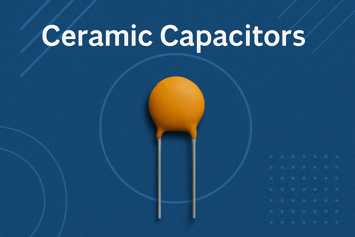
While the single-channel TL071 and dual-channel TL072 share an identical internal JFET-input differential front-end—delivering an input impedance of 1012 Ω, a typical slew rate of 13 V/μs[1], and a broadband input voltage noise of approximately 18 nV/Hz at 1 kHz—they are not pin-compatible and serve distinct circuit architectures.The TL071 provides dedicated external DC offset nulling pins (Pins 1 and 5) and absolute physical channel isolation, making it essential for precision DC-coupled instrumentation, modular synthesizer control voltage (CV) paths, and high-gain audio input stages. The TL072 packs two independent op-amps into the same 8-pin footprint, doubling board routing density for stereo audio preamps, active filters, and compact pedal buffers. However, it sacrifices manual offset trimming and introduces high-frequency capacitive crosstalk, common-mode power rail coupling, and die-level thermal feedback between channels.1. Quick Summary & Engineering Decision FrameworkKey Takeaway: Choosing between the TL071 and TL072 balances channel density against DC precision: the TL071 enables manual offset nulling and complete physical isolation, while the dual TL072 halves board space for AC-coupled audio paths.Need JFET High-Z Front-End? (1012 Ω, Low Bias Current)Single Stage / High-Z Direct-Coupled CV Path:Select TL071 (Single)Dedicated DC offset nullZero inter-channel bleedAbsolute physical isolationMulti-Stage / Stereo Path Space-Constrained Board:Select TL072 (Dual)2 channels per 8-pin packLower routing overheadIdeal for AC-coupled audioWhen to Select the TL071Direct-Coupled DC Circuits: Where input offset voltage (VOS) cannot be blocked by series capacitors and must be zeroed using an external trimmer potentiometer.Modular Synthesizer CV Processing: In 1V/Octave pitch-tracking circuits where a 3 mV DC offset introduces audible musical mistuning.Ultra-High-Gain Audio Front-Ends: In moving-magnet phono stages, microphone preamplifiers, or active instrumentation where running high-gain amplification alongside another channel on the same silicon die risks oscillation or inter-channel bleed.Sub-Module Thermal Isolation: Applications where output stage heat dissipation must remain isolated from sensitive high-impedance source nodes.When to Select the TL072Stereo Line-Level Preamplifiers: Where left and right line-level audio signals require identical amplification within a compact footprint.Active Multi-Pole Filters: Standard 2-pole or 4-pole Sallen-Key and state-variable topologies where cascaded operational amplifier stages share a tight circuit loop.Space-Constrained Audio Gear: Guitar effect pedals, multichannel mixing desks, and Eurorack utility buffers where PCB real estate and component count dictate layout economy.AC-Coupled Audio Paths: Circuits where DC-blocking capacitors isolate downstream stages, making external offset trimming unnecessary.Comparative Specification MatrixEngineering ParameterTL071 (Single Op-Amp)TL072 (Dual Op-Amp)Design ImplicationNumber of Channels12TL072 doubles functional board density.Package OptionsDIP-8, SOIC-8, TSSOP-8DIP-8, SOIC-8, TSSOP-8Identical standard packaging footprints.Pinout InterchangeabilityNon-compatibleIndustry-standard dual pinoutDirect cross-insertion causes circuit destruction.DC Offset TrimmingYes (Pins 1 & 5)None (Pin-starved)TL072 requires external summing for DC nulling.Quiescent Current (Iq, typ)1.4 mA total2.8 mA total (1.4 mA/ch)TL072 draws double the battery current in idle state.Slew Rate (typ, 25∘C)13 V/μs (Legacy) / 20 V/μs (H)13 V/μs (Legacy) / 20 V/μs (H)Full-power audio bandwidth identical per channel.Gain Bandwidth Product3 MHz typical3 MHz typical[2]Matching high-frequency gain profiles.Input Impedance (ZIN)1012 Ω1012 ΩMatched JFET input stages eliminate transducer loading.Broadband Noise (1 kHz)18 nV/Hz18 nV/HzIdentical input noise voltage floor per channel.Inter-Channel CrosstalkNon-existent (Discrete die)~120 dB (DC/100 Hz); degrades −6 dB/octTL072 exhibits capacitive HF bleed above 1 kHz.Exclusion ProfileHigh-density multi-stage routingDirect-coupled precision DC circuitsMatch component selection to circuit coupling mode.Note: Baseline operating conditions are VCC=±15 V and TA=25∘C unless specified.2. The "8-Pin Trap": Pinout Incompatibility and Drop-In HazardsA common mistake during repair or prototyping is treating the TL071 and TL072 as interchangeable because both share the standard 8-pin DIP or SOIC package. Plugging a TL072 into a TL071 socket (or vice versa) can cause circuit malfunction or permanently damage the semiconductor.Pinout Comparison: TL071 Single vs TL072 Dual Op-AmpSide-by-Side Pinout Collision AnalysisPin NumberTL071 Pin FunctionTL072 Pin FunctionCollision Risk when TL072 is Inserted in TL071 SocketPin 1Offset Null 1Output AHigh Risk: Output A drives current directly into the internal balance nodes of the input stage.Pin 2Inverting Input (-)Inverting Input A (-)Matched functionality (Channel A).Pin 3Non-Inverting Input (+)Non-Inverting Input A (+)Matched functionality (Channel A).Pin 4Negative Supply (VCC−)Negative Supply (VCC−)Matched power rail ground/negative reference.Pin 5Offset Null 2Non-Inverting Input B (+)High Risk: Channel B input is tied directly to the TL071 offset trimmer wiper network.Pin 6OutputInverting Input B (-)High Risk: The circuit's main output node is shorted to the high-impedance input of Channel B.Pin 7Positive Supply (VCC+)Output BSevere Risk: The active output stage of Channel B is tied directly to the positive power rail (VCC+).Pin 8No Internal Connection (NC)Positive Supply (VCC+)Severe Risk: The positive power rail is routed to an unassigned pad, leaving the IC unpowered or misbiasing pins.Failure Modes During Socket SwappingInserting a TL072 into a TL071 Socket: Pin 7 is typically connected to +15V on a TL071 board. In a TL072, Pin 7 is the low-impedance Output B. Connecting the positive supply rail directly to an active op-amp output forces high current through the internal output stage, triggering thermal breakdown. Pin 8, which provides VCC+ on the TL072, sits in a dead pad (NC), starving the dual IC of balanced positive supply current and causing unpredictable latch-up.Inserting a TL071 into a TL072 Socket: Pin 8 carries +15V on a TL072 board, but lands on the NC pin of a TL071. Pin 7 (the actual VCC+ pin of the TL071) lands on the Output B trace of the board. The TL071 receives no positive power supply, while downstream circuitry on Output B is back-fed by parasitic leakage currents.When this mismatch occurs, board Pin 7 (+15V rail) connects directly to Pin 7 of the TL072 (Output B), resulting in a high-current short that overheats the IC, while Board Pin 8 (No Connect) connects to Pin 8 of the TL072 (VCC+), causing power starvation and circuit failure.Bench Servicing and Adapter ProtocolsWhen servicing vintage audio equipment where single-channel op-amps are obsolete or physically unavailable, dual-to-single conversion requires a specialized daughterboard. These adapter PCBs cross Pin 8 (VCC+ on the dual) back to Pin 7 on the single footprint, isolate Pins 1 and 5 from the external null circuitry, and terminate the unused second channel into a stable, non-oscillating feedback loop.3. Core Electrical Architecture: Where Single and Dual Channels MatchThe TL071 and TL072 utilize the same monolithic JFET-input operational amplifier core. Per channel, their internal schematic topology is identical: a matched pair of high-voltage P-channel JFETs feeding a bipolar intermediate gain stage and a complementary Class-AB output driver.For practical layout implementation, examine UTMEL's guide on the TL071 op-amp[8] for single-channel topologies, and reference UTMEL's guide on the TL072 op-amp for dual-channel audio preamplifiers.The JFET Front-End AdvantageThe primary design reason to choose either part is input impedance. The reverse-biased P-N junctions of the input JFET gates yield an input resistance of 1012 Ω (1 TΩ) paired with an input bias current measured in picoamps: typical room-temperature values sit between 30 pA and 65 pA[3].Minimizing Source Loading: High-impedance transducers—such as electric guitar passive magnetic pickups (5 kΩ−15 kΩ series DC resistance with high inductance) or raw piezoelectric sensors (>1 MΩ)—suffer severe high-frequency attenuation ("tone suck") when terminated into standard bipolar op-amps (such as the NE5532 or LM833, whose bias currents range from 200 nA to 800 nA). The TL07x JFET gate draws negligible current, preserving source frequency response.Thermal Gate Leakage: JFET input bias current doubles roughly every 10∘C rise in silicon junction temperature. In high-temperature audio chassis, input bias current can rise from 65 pA at 25∘C to over 2 nA at 70∘C.Matched AC Signal ParametersBoth amplifiers share identical high-speed AC dynamics:Slew Rate (13 V/μs): Standard line-level professional audio (+4 dBu=1.228 VRMS, peaking around 3.5 Vpk) across the 20 kHz band requires a minimum slew rate: SRmin=2π×20,000 Hz×3.5 V≈0.44 V/μs Operating at 13 V/μs provides a comfortable margin above this threshold, eliminating slew-rate-induced distortion across the audible spectrum.Total Harmonic Distortion (THD): Maintains low distortion figures, typically between $0.003\%$ and $0.01\%$ at 1 kHz under standard audio loading (RL≥2 kΩ).Gain Bandwidth Product (GBW): A unity-gain bandwidth of 3 MHz allows for stable open-loop gain reserves across the typical audio band.Quiescent Current and Battery BudgetsBecause the TL072 contains two identical amplifier cores on a single silicon die, its supply current is twice that of the single-channel TL071:TL071 Quiescent Draw: 1.4 mA typical (2.5 mA maximum).TL072 Quiescent Draw: 2.8 mA typical (5.0 mA maximum).In portable, battery-powered equipment—such as 9V guitar effect pedals running on a standard alkaline battery (500 mAh nominal capacity to a 7.0 V cutoff):RuntimeTL071≈500 mAh1.4 mA≈357 hours RuntimeTL072≈500 mAh2.8 mA≈178 hoursSelecting a dual op-amp when only a single channel is needed halves battery life, increases baseline thermal dissipation, and adds unnecessary parasitic risk.4. DC Offset Nulling vs. Channel Density: The Real Design Trade-OffKey Takeaway: The core operational difference lies in DC precision management—the TL071 features dedicated offset null pins (Pins 1 and 5) for sub-millivolt calibration, while the pin-constrained TL072 cannot accommodate on-chip trimming.TL071 External DC Offset Trimming TopologyThe Physics of Input Offset Voltage (VOS)Due to manufacturing tolerances in ion implantation and physical gate geometry on monolithic silicon, the two JFETs in the input differential pair never match completely. This asymmetry manifests as an Input Offset Voltage (VOS), which typically measures 3 mV (with maximum values reaching 6 mV to 10 mV on standard commercial grades) and exhibits a thermal drift coefficient of approximately 18 μV/∘C.The TL071 Trimming SolutionThe TL071 routes the source/emitter connections of the input stage's active load to Pin 1 (Offset Null 1) and Pin 5 (Offset Null 2).To trim DC offset to zero:Connect a 50 kΩ to 100 kΩ non-inductive linear potentiometer between Pins 1 and 5.Connect the potentiometer wiper directly to the negative supply rail (VCC−).Ground the inputs through equivalent source resistances and adjust the wiper until the output reads 0.0 V DC.This adjustment alters the current balance through the internal load resistors, pulling output offset within microvolts of ground.Why the TL072 Cannot Support On-Chip TrimmingAn 8-pin package imposes a strict physical limit:2 Pins for Power Supplies (VCC+,VCC−)3 Pins for Channel A (IN+,IN−,OUT)3 Pins for Channel B (IN+,IN−,OUT)The package is fully allocated, leaving no pins for external offset nulling.Real-World Engineering ConsequencesAC-Coupled Audio Circuits: Offset is blocked by series capacitors, so no DC offset nulling is needed. The TL072 is ideal for board density.Direct-Coupled / CV Circuits: DC offset is amplified by stage gain, which triggers pitch drift in synth CV paths and causes "scratchy pot" DC artifacts. A TL071 with a null pot is mandatory.AC-Coupled Audio Paths (TL072 Preferred): In standard audio circuitry where capacitors isolate intermediate stages, a 3 mV−6 mV DC offset is blocked by downstream capacitors, preventing DC current from entering subsequent stages. The TL072 is the standard industry choice here because board space and channel density outweigh DC trim capabilities.Direct-Coupled CV and Instrumentation Paths (TL071 Mandatory): In synthesizer control voltage (CV) processing (e.g., 1 V/octave exponential converters), a 3 mV offset shifts pitch by: ΔCents=1200×0.003 V1.0 V=3.6 Cents Cascading multiple un-nulled stages can shift tuning out of acceptable tolerance. Furthermore, in direct-coupled audio topologies, passing DC offset currents across gain potentiometers causes audible "scratching" noises during adjustment, as well as transient "thumps" during mechanical bypass switching.5. Audio Realities: Channel Separation, Crosstalk, and Thermal InterplayKey Takeaway: Dual op-amps do not offer total channel isolation; parasitic pin capacitance, common-mode power rail impedance, and die-level thermal feedback cause TL072 channel separation to degrade above 1 kHz.Inter Miami CF vs. New York City FC | Full Match Highlights | Miami Mayhem!The "120 dB Isolation" Datasheet MythManufacturer documentation often lists a channel separation figure of 120 dB for the TL072. However, this figure applies strictly at DC and low frequencies (100 Hz to 1 kHz) under specific open-loop conditions (AVD=100,TA=25∘C). It does not reflect practical high-frequency performance in real-world circuit board layouts.Mechanisms of High-Frequency CrosstalkStray Inter-Pin Capacitance: In an 8-pin DIP or SOIC package, adjacent lead-frame fingers and internal bond wires run parallel over millimetric distances, introducing roughly 1 pF of parasitic stray capacitance between adjacent pins. Pin 1 (Output A) sits directly adjacent to Pin 2 (Inverting Input A), while Pin 7 (Output B) runs adjacent to Pin 6 (Inverting Input B). In high-impedance circuits, capacitive coupling rolls off channel separation at a rate of −6 dB/octave above 1 kHz. In audio circuits with high source impedances (>50 kΩ) operating at 10 kHz−20 kHz, real-world channel isolation can drop below 70 dB[5].Shared Power Rail Impedance: Both amplifier stages inside the TL072 share single bond wires to Pin 8 (VCC+) and Pin 4 (VCC−). When Channel A drives a heavy, low-impedance load (e.g., 600 Ω headphones or long cable runs), its dynamic current demands create small voltage drops across the parasitic inductance and resistance of those bond wires. This modulates the supply rails of Channel B, introducing signal bleeding between channels unless decoupling is carefully managed.Die-Level Thermal Gradients: When Channel A outputs significant power, its output transistors warm the silicon substrate locally. The resulting heat waves travel across the die, creating microscopic temperature gradients across the differential input transistors of Channel B. This thermal feedback induces low-frequency distortion and DC baseline shifts in the adjacent channel.Layout Rules to Mitigate CrosstalkMandate Separate TL071 Packages: For mastering-grade stereo channels, high-gain moving-magnet phono preamplifiers (>40 dB gain), and multi-channel microphone preamps, physical separation using discrete TL071s eliminates silicon thermal feedback and intra-package capacitive coupling.Use TL072 for Series Processing: The TL072 works well when both internal amplifiers handle the same signal in series (e.g., Stage 1 provides gain, Stage 2 buffers or filters). Any leakage between the two stages remains in-phase and coherent with the main signal path.PCB Decoupling Protocol: Place a 100 nF high-frequency ceramic capacitor within 3 mm−5 mm of Pins 4 and 8, running directly to a solid, low-impedance ground plane. Supplement this with a 10 μF electrolytic or tantalum capacitor nearby to suppress low-frequency rail modulation.6. Circuit Protection & Servicing Pitfalls: Unused Termination and Phase ReversalOp-Amp Protection: Termination and Anti-Phase Reversal MeasuresThe Unused Channel Hazard in the TL072When an engineer uses only one half of a TL072, leaving the unused amplifier pins floating or disconnected is a critical error.What Happens When Pins Float: The ultra-high input impedance (1012 Ω) picks up stray electrostatic charge, driving the inputs toward opposite power supply rails. The amplifier's high open-loop gain pushes the output into hard saturation against either VCC+ or VCC−. In this saturated state, the op-amp draws maximum internal supply current[7], overheats the package, reduces available power rail headroom, and injects high-frequency parasitic noise into the active operational amplifier stage.Why Grounding Both Inputs Fails: Grounding both IN+ and $IN-$ directly to 0 V does not solve the problem. The input offset voltage (VOS) acts as a permanent differential DC error. Amplified by open-loop gain (AVOL≈100 dB), this offset drives the output into hard rail saturation.Recommended Unused Channel TerminationDual-Supply Systems (±15V):Connect the unused output directly to its inverting input ($IN-$), configuring the stage as a unity-gain voltage follower.Connect the non-inverting input (IN+) directly to the system ground plane (0 V).Result: The amplifier output remains stably biased at 0.0 V DC[6], operating within its linear common-mode range with minimal quiescent current draw.Single-Supply Systems (+9V or +12V):Connect the output directly to the inverting input ($IN-$).Connect the non-inverting input (IN+) to a stable mid-rail reference voltage (virtual ground, VCC/2), generated via a resistor divider and decoupling capacitor.Never tie inputs to the supply rails or leave them floating.The JFET Phase Reversal TrapA characteristic failure mode of legacy JFET operational amplifiers is input phase reversal (output inversion):Silicon Physics: The common-mode input voltage range (VICR) of the legacy TL07x series extends from (VCC−+4 V) up to VCC+. If an input voltage swings too close to the negative supply rail (within roughly 3 V to 4 V of VCC−), the internal P-channel JFET gate-drain P-N junction loses its reverse bias and becomes forward-biased[4].Circuit Consequence: Forward-biasing this junction flips the internal differential balance. The op-amp output suddenly swings away from the negative rail and latches hard against the positive rail (VCC+). In high-gain audio power amplifiers, this sudden positive latch-up can damage speaker voice coils or saturate downstream transformer cores.Bench Protection: Install a current-limiting resistor (10 kΩ) in series with the non-inverting input, paired with external low-leakage Schottky clamping diodes to prevent input voltages from falling within 4 V of the negative supply rail.7. Component Sourcing & Evolution: Legacy TL07x vs. Modern TL07xH RevisionsWhen sourcing replacements for repair work or initiating a new hardware layout, engineers should be aware that modern production components differ from legacy 1980s-era parts.Parameter / FeatureLegacy TL07x (1970s - 2010s)Modern TL07xH SeriesMaximum Supply Voltage30V−36V total (±15V to ±18V)40V total (±20V)Typical Slew Rate13 V/μs typical20 V/μs typicalTypical Input Offset (VOS)3 mV typ (up to 10 mV)1 mV typ (laser trimmed)Phase Reversal SusceptibilityProne to JFET Phase ReversalIntegrated Phase Reversal ImmunitySemiconductor ProcessStandard bipolar-JFET processModernized high-voltage CMOS/JFETTexas Instruments introduced the modernized TL071H and TL072H families, fabricated on upgraded high-voltage semiconductor processes:Expanded Supply Voltage: Total supply voltage headroom increases from the legacy 30V−36V limit (±15V or ±18V) to a full 40V absolute maximum rating (±20V split supply).Upgraded Slew Rate: Typical slew rate is boosted from 13 V/μs to 20 V/μs, expanding the large-signal bandwidth margin.Lower DC Input Offset: Modern laser trimming reduces typical room-temperature input offset voltage from 3 mV down to 1 mV.Built-in Phase Reversal Protection: The "H" series features integrated internal clamp circuitry that prevents output phase inversion even if input signals drop below the negative common-mode threshold.Servicing Vintage Gear: Drop-In ViabilityModern "H" variants (TL071H, TL072H) use the standard pinouts and act as functional replacements for vintage audio consoles, effect pedals, and synthesizers. They maintain the JFET input impedance (>1012 Ω) while improving slew margin, offset drift, and latch-up resistance.Counterfeit Warning: Sourcing components from unverified open-market vendors carries risk. Counterfeiters frequently re-mark general-purpose bipolar op-amps (such as the LM358 or LM741) as TL071 or TL072 parts. Installing a re-marked bipolar chip in a high-impedance guitar circuit creates immediate source loading, bandwidth loss, and high input bias current drift. Always verify input pin resistance with a bench multimeter: a genuine JFET input measures as an open circuit (several gigohms) to ground, whereas a bipolar input displays readable P-N junction diode drops.8. Frequently Asked Questions (FAQ)Can I replace a TL071 with an NE5534 or LM741 in an existing circuit?Not without careful circuit evaluation. The LM741 is obsolete for audio: it has a slow slew rate (0.5 V/μs), a narrow bandwidth (1 MHz), high input noise, and bipolar inputs that load high-impedance sources.The NE5534 is an audio-grade operational amplifier with low voltage noise (3.5 nV/Hz), but it relies on a bipolar input stage that draws significant input bias current (500 nA typical vs. 65 pA for the TL071). If inserted into a high-impedance circuit (e.g., a guitar tone stack), this high bias current creates large DC offset errors across passive resistors. Additionally, the NE5534 is only stable for gains ≥3; running it as a unity-gain buffer requires an external 22 pF compensation capacitor across Pins 5 and 8 to prevent high-frequency oscillation.Can I swap a TL072 with an RC4558 or NE5532 in guitar pedals?Direct substitution works without pin modification because all three share the standard dual op-amp pinout. However, the circuit's tone will often change noticeably.The RC4558 and NE5532 use bipolar inputs. In circuits where the op-amp directly buffers passive guitar pickups without an intermediate transistor stage, the lower input impedance (300 kΩ for the 4558 vs. 1012 Ω for the TL072) loads the guitar pickup, attenuating high-frequency detail. Conversely, in low-impedance line-level stages, an NE5532 can deliver a lower broadband noise floor than a TL072 because its voltage noise is lower (5 nV/Hz vs. 18 nV/Hz).How much faster does a TL072 drain a 9V battery compared to a TL071?Under identical quiescent operating conditions, the TL072 draws approximately double the current of a TL071 (2.8 mA vs. 1.4 mA).On a standard 500 mAh 9V alkaline battery, a single-channel TL071 can run continuously for approximately 350 hours, whereas a dual-channel TL072 depletes the same battery in roughly 175 hours. For battery-powered field gear or pedalboards, avoid using dual op-amps with an unused channel when a single-channel op-amp satisfies the circuit requirements.Does the single-channel TL071 sound cleaner than the TL072?In an isolated, single-ended signal path, there is no audible difference. The internal silicon topology, slew rate (13 V/μs), total harmonic distortion ($0.003\%$), and noise spectral density (18 nV/Hz) are matched per channel across both parts.The TL071 only performs "cleaner" in circuits where a dual TL072 suffers from layout-induced degradation—such as high-frequency capacitive crosstalk, dynamic power rail modulation, or thermal coupling from a heavily loaded second channel.Can I use just one half of a TL072 and leave the other half disconnected?No. Leaving an unused op-amp stage floating allows high-impedance inputs to pick up electrostatic noise, driving the output into hard saturation against the power supply rails. This increases power consumption, generates package heat, and couples parasitic oscillation into the active channel. Unused channels should always be terminated as a unity-gain voltage follower with the non-inverting input tied to a mid-rail or ground reference.9. Engineering Pre-Flight & Bench Verification ChecklistBefore releasing a PCB to fabrication or closing an audio chassis after servicing, review the following design criteria:[ ] Pinout Verification: Confirmed that the schematic pin assignments match the physical IC package (TL071 single vs. TL072 dual; Pins 1 & 5 confirmed for offset null vs. dual I/O).[ ] DC Trimming Verification: If DC precision or direct coupling is required, confirmed whether a TL071 with a 50 kΩ−100 kΩ balance trimmer to VCC− is implemented, or if AC-coupling capacitors are placed to block TL072 offset drift.[ ] Unused Channel Termination: Ensured every unused amplifier stage in dual TL072 packages is configured as a unity-gain follower with the non-inverting input tied to a mid-rail/ground reference.[ ] Common-Mode Boundary Review: Confirmed that input signal swings never drop within 4V of the negative supply rail (VCC−) to prevent JFET phase reversal latch-up (or verified use of TL07xH series).[ ] Supply Rail Decoupling: Placed 100 nF surface-mount or ceramic disc bypass capacitors within 5 mm of Pins 4 (VCC−) and 7/8 (VCC+) directly to a low-impedance ground plane.[ ] Crosstalk & Isolation Audit: Verified that high-gain preamplification stages (e.g., >40 dB) utilize separate TL071 single packages or implement strict ground-shield routing between TL072 sections.Sources and references used for this guideTL071 data sheet, product information and support | TI.comSource type: official company documentationUsed for: Primary electrical specifications, single-channel pinout, offset nulling circuit, and modern TL071H updates.Caution: Manufacturer source; reflects specified factory test conditions (TA=25°C, VCC=±15V).TL072 data sheet, product information and support | TI.comSource type: official company documentationUsed for: Dual-channel electrical characteristics, dual pinout configurations, package options, and modern TL072H specifications.Caution: Manufacturer source; test conditions must be cited when referencing maximum ratings.Low noise JFET single operational amplifier - STMicroelectronicsSource type: official company documentationUsed for: Independent manufacturer verification of core JFET electrical characteristics (slew rate, GBW, input impedance).Caution: Multi-vendor standard device; slight parametric variances exist between manufacturers.Op Amps for Everyone Design Guide (Rev. B) - MITSource type: research sourceUsed for: Circuit stability analysis, decoupling guidelines, feedback loop stability, and JFET input phase-reversal theory.Caution: Academic/engineering textbook; provides theoretical design rules rather than specific product catalogs.Op amps in small-signal audio design - Part 1 - EE TimesSource type: reputable professional sourceUsed for: Audio engineering trade-offs between single and dual op-amps, inter-channel crosstalk, and distortion properties in audio mixing.Caution: Authored by Douglas Self; focuses specifically on small-signal audio applications.Properly terminating an unused op amp - EDNSource type: reputable professional sourceUsed for: Engineering guidelines and schematic topologies for terminating unused dual op-amp stages to prevent oscillation.Caution: Trade publication article; schematic implementation must account for single-supply vs dual-supply configurations.Avoiding Noise and Power Problems with Unused Op Amps - Analog DevicesSource type: official company documentationUsed for: Detailed electrical failure analysis of floating inputs, saturation rail currents, and parasitic oscillation in multi-channel op-amps.Caution: Competitor manufacturer application note; principles apply universally across analog operational amplifiers.TL071: Detailed Datasheet, Pinout, and Alternatives Guide - UTMELSource type: vendor articleUsed for: Practical component pin identification, breadboard setup, and application overview for single JFET op-amps.Caution: Commercial distributor article; use for basic pinout and application context, not primary parametric verification.
On 2026-10-16


![ENC624J600-I/PT microcontroller: Datasheet, Features, Application[FAQ]](https://static.kynix.net/imgs/BlogImage-v/20230316173617653713.jpg)
![ATMEGA1280-16AU microcontroller: Datasheet, Features, Application[FAQ]](https://static.kynix.net/imgs/BlogImage-v/20230309165108141686.png)
![STM8S207CBT6 Microcontroller: Datasheet, Features, Application[FAQ]](https://static.kynix.net/imgs/BlogImage-v/20230309165213605373.png)
![2N7002P Mosfet: Datasheet, Pinout, Features [FAQ]](https://static.kynix.net/imgs/BlogImage-v/ky_bg_head_20211021173017.jpg)
![L298N Motor Driver: Datasheet, Arduino, Circuit [Video&FAQ]](https://static.kynix.net/imgs/BlogImage-v/ky_bg_head_20211021154504.jpg)
![MCP2515-I/P CAN Controller: CAD Models, Datasheet, Features [Video&FAQ]](https://static.kynix.net/imgs/BlogImage-v/ky_bg_head_20211021153456.jpg)