Efficiently connecting the STM32G491RET6 ensures your design achieves reliable performance. This high-performance microcontroller, based on the Cortex-M4 architecture, offers advanced features for demanding applications. Proper integration prevents issues like signal interference or power instability, which can compromise functionality.
Start by understanding the requirements of the STM32 and the components you plan to use. Choose compatible microcontrollers and peripherals. Study datasheets to identify pin configurations and electrical characteristics. A thoughtful approach to integration allows you to unlock the full potential of your STM32G491RET6 design.
Preparing for STM32G491RET6 Integration
Selecting Compatible Components for STM32
Choosing the right components is critical for a successful STM32 integration. You should prioritize components that are tested for reliability and stability. STM32 microcontrollers, including the STM32G491RET6, are known for their dependable performance in various applications. This makes them an excellent choice for projects requiring consistent operation.
When selecting components, avoid common mistakes. For example, purchasing a display without reviewing its specifications or compatibility can lead to costly redesigns. Neglecting to integrate the display early in the system design may result in mechanical and firmware issues. The table below highlights some common pitfalls and their consequences:
| Mistake |
Description |
Consequences |
| Choosing a random display |
Purchasing the cheapest available display without considering specifications |
Costly redesigns, certification issues, or unsuitability for the target environment. |
| Ignoring the display in design |
Focusing on the device operation while neglecting early display integration |
Mechanical and firmware redesigns, changes to connectors, and compatibility issues. |
| Using poorly documented displays |
Selecting touchscreens with no available drivers, firmware, or software examples |
Time loss, lack of support, and potential failure to integrate. |
By carefully evaluating the specifications and documentation of each component, you can avoid these challenges and ensure smooth integration.
Reading Datasheets and Application Notes
Datasheets and application notes are your best friends when working with STM32 microcontrollers. These documents provide detailed information about electrical characteristics, pin configurations, and performance metrics. For example, the STM32F100VCT6B datasheet reveals that it supports a maximum clock frequency of 24 MHz and includes up to 512 Kbytes of Flash memory for program storage. It also features 32 Kbytes of SRAM for temporary data storage during execution.
Understanding the clock system and optimizing memory usage are essential for effective integration. Additionally, STM32 microcontrollers support low-power modes, which can enhance energy efficiency in your design. Leveraging the STM32 ecosystem, including tools like STM32CubeMX, can further streamline your development process.
Setting Up the Development Environment with STM32CubeMX
STM32CubeMX is a powerful tool that simplifies the development process for STM32 microcontrollers. It allows you to configure peripherals, generate initialization code, and manage pin assignments with ease. To get started, download and install STM32CubeMX from the official STMicroelectronics website. Once installed, follow these steps:
- Create a New Project: Select your STM32 microcontroller model, such as the STM32G491RET6, from the list of available devices.
- Configure Peripherals: Use the graphical interface to enable and configure peripherals like UART, SPI, or the analog-to-digital converter.
- Generate Code: After configuring the peripherals, generate the initialization code. This code serves as the foundation for your application.
- Import into IDE: Import the generated code into your preferred Integrated Development Environment (IDE), such as STM32CubeIDE or Keil.
STM32CubeMX also supports advanced features like ADC calibration and trigger configuration. These features are particularly useful when working with the analog-to-digital converter. For example, you can adjust the ADC sampling time and rate to optimize data conversion for your application. Proper calibration ensures accurate digital data output, which is crucial for high-performance designs.
By setting up your development environment correctly, you can save time and reduce errors during the integration process.
Power Supply and Circuit Design for STM32G491RET6
Ensuring Proper Voltage Levels and Regulation
Maintaining proper voltage levels is critical for the STM32G491RET6 to function reliably. This microcontroller operates within specific voltage thresholds, and exceeding or dropping below these levels can cause instability. The table below highlights key voltage parameters you should monitor:
| Voltage Type |
Description |
Importance |
| VPOR/PDR |
Minimum operating voltage threshold (1.7V-1.8V) |
Prevents the microcontroller from operating below safe levels. |
| VBOR |
Brownout reset threshold |
Ensures the system remains in reset until voltage is adequate. |
| VPVD |
Programmable voltage detector threshold |
Monitors VDD to ensure it stays above a set level. |
To regulate voltage, use a high-quality voltage regulator. This ensures the STM32 receives a stable power supply, even during load fluctuations. Additionally, consider implementing a programmable voltage detector to monitor and respond to voltage drops in real time.
Using Decoupling Capacitors for Stability
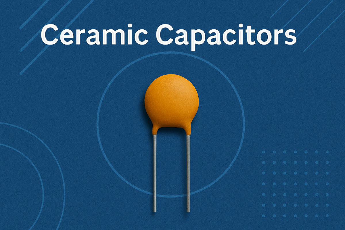
Decoupling capacitors play a vital role in stabilizing the power supply for STM32 circuits. These components filter out noise and smooth voltage fluctuations, ensuring consistent operation. For best results, use capacitors with low ESR (Equivalent Series Resistance) and ESL (Equivalent Series Inductance). Place them close to the STM32's power pins to minimize parasitic effects and current loops.
- Decoupling capacitors reduce noise generated by high-speed switching circuits.
- Proper placement improves stability and prevents voltage spikes.
- Low ESR capacitors enhance performance in high-frequency applications.
For example, placing a 0.1 μF ceramic capacitor near the VDD pin can significantly improve stability. This simple addition ensures the STM32 operates without interruptions caused by transient voltage changes.
Designing a PCB for STM32 Integration
A well-designed PCB is essential for integrating the STM32G491RET6 into your application. Start by organizing the layout to minimize noise and interference. Keep power and ground planes separate to reduce electromagnetic interference (EMI). Include an onboard 3.3V regulator to provide a stable power source for the STM32.
Key design practices include:
- Adding a power LED and reset button for usability.
- Ensuring low power consumption for battery-operated devices.
- Supporting multiple communication interfaces for flexibility.
For example, a PCB with a dedicated analog channel for ADC operations can improve signal integrity. This is especially important when using the STM32's ADC modes of operation, as it ensures accurate conversion and high-resolution data output. Proper calibration of the ADC sampling time and rate further enhances performance.
By following these guidelines, you can create a robust PCB that supports the STM32's advanced features while maintaining system stability.
Communication Interfaces for STM32G491RET6
Connecting Peripherals via UART
UART (Universal Asynchronous Receiver-Transmitter) is one of the simplest ways to connect peripherals to your STM32. It enables reliable serial communication between your microcontroller and external components like sensors, displays, or other microcontrollers. You can configure UART easily using STM32CubeMX, which allows you to set baud rates, parity, and stop bits.
Here are some practical examples of UART's effectiveness:
- A bus analyzer project used UART for data analysis, demonstrating its real-world application.
- A functional receiver/transmitter was implemented successfully, showcasing UART's ease of use with STM32.
- Challenges with USB integration highlighted UART's simplicity compared to other protocols.
When using UART, ensure proper calibration of baud rates to match the connected device. This avoids data loss during transmission. Additionally, consider using DMA (Direct Memory Access) to offload data transfer tasks from the CPU, improving efficiency.
Using SPI for High-Speed Data Transfer
SPI (Serial Peripheral Interface) is ideal for high-speed data transfer in STM32 systems. It uses a master-slave architecture and supports full-duplex communication, making it faster and more efficient than I2C for many applications. For example, SPI is commonly used to connect high-resolution displays or ADCs requiring precise sampling and conversion.
The table below compares SPI and I2C to highlight SPI's advantages:
| Feature |
SPI |
I2C |
| Data Transfer Speed |
Up to 100 MHz (modern) |
Up to 400 kHz (standard) |
| Architecture |
Master-slave |
Multi-master |
| Complexity |
Simple (4 lines) |
More complex (addressing) |
| Latency |
Low (full-duplex) |
Higher (overhead) |
| Overhead |
Minimal |
Higher |
| Timing Control |
Precise |
Less precise |
| Flexibility |
High (multiple slaves) |
Limited |
To optimize SPI performance, configure the clock polarity and phase correctly. Use STM32CubeMX to set up SPI channels and enable DMA for faster data transfer. Proper calibration of the SPI clock ensures accurate timing and minimizes errors.
Interfacing with I2C Devices
I2C (Inter-Integrated Circuit) is a versatile protocol for connecting multiple devices to your STM32 using just two lines: SDA (data) and SCL (clock). It is particularly useful for low-speed communication with components like EEPROMs, temperature sensors, or ADCs in example applications requiring moderate resolution.
When interfacing with I2C devices, ensure proper pull-up resistors are added to the SDA and SCL lines. These resistors maintain signal integrity and prevent communication errors. STM32CubeMX simplifies I2C configuration by allowing you to set the clock speed and address mode. For applications requiring precise sampling and conversion, calibrate the I2C timing parameters to match the connected device's specifications.
I2C's multi-master capability allows you to connect multiple STM32 microcontrollers or peripherals on the same bus. However, its higher overhead and slower speed compared to SPI make it less suitable for high-resolution or high-speed data transfer tasks.
General-Purpose Input/Output (GPIO) pins are essential for connecting your STM32 microcontroller to external devices. These pins allow you to send and receive digital signals, making them versatile for various applications like reading sensor data or controlling LEDs. Configuring GPIO correctly ensures reliable communication and prevents unexpected behavior.
Setting GPIO Modes and Functions
Each GPIO pin on the STM32 can operate in different modes, such as input, output, alternate function, or analog. You can configure these modes using the GPIOx_MODER register. For example, setting a pin as an output allows it to control external devices like motors or displays. On the other hand, configuring a pin as an input enables it to read signals from sensors or buttons.
The table below summarizes key GPIO registers and their functions:
| Register |
Description |
| GPIOx_MODER |
Sets the pin mode (input, output, alternate function, or analog). |
| GPIOx_OSPEEDR |
Controls the slew rate of the output signal for the pin. |
| GPIOx_PUPDR |
Configures pull-up or pull-down resistors for each pin. |
| GPIOx_OTYPER |
Determines the output type (push-pull or open-drain) for output pins. |
| GPIOx_IDR |
Reads the input level of the pin. |
| GPIOx_ODR |
Writes the output level of the pin. |
| GPIOx_BSRR |
Efficiently sets or resets individual bits in the ODR register. |
Practical Tips for GPIO Configuration
-
Input Configuration: Use the GPIOx_IDR register to read the input level of a pin. For example, when connecting a button, configure the pin as an input and enable a pull-up resistor using the GPIOx_PUPDR register. This ensures the pin reads a stable high or low signal when the button is pressed or released.
-
Output Configuration: Use the GPIOx_ODR register to set the output level of a pin. For instance, to turn on an LED, configure the pin as an output and write a high signal to the ODR register. You can also use the GPIOx_BSRR register for faster bit manipulation.
-
Direct Register Access: Accessing GPIO registers directly provides faster operations compared to using HAL (Hardware Abstraction Layer) functions. This approach is especially useful in time-sensitive applications.
Testing GPIO Operations
After configuring GPIO, test the setup to verify its functionality. For input pins, check if the microcontroller correctly detects changes in the signal. For output pins, confirm that the connected device responds as expected. Monitoring the GPIOx_IDR and GPIOx_ODR registers during testing helps identify any issues.
By mastering GPIO configuration, you can unlock the full potential of your STM32G491RET6 microcontroller. Whether you're building a simple LED controller or a complex sensor interface, proper GPIO setup ensures your project runs smoothly.
Debugging and Testing STM32G491RET6 Connections
Verifying Electrical Connections
Before running your STM32G491RET6-based system, ensure all electrical connections are correct. Start by checking the power supply. Confirm that the voltage levels match the microcontroller's requirements. Use a multimeter to measure the voltage at the VDD and GND pins. This step prevents potential damage caused by incorrect power levels.
Inspect the connections between the STM32 and other components. Verify that the GPIO pins are correctly wired to external devices. For example, if you are using an ADC for data conversion, ensure the analog input pin is connected to the correct signal source. Loose or incorrect connections can lead to signal loss or inaccurate sampling.
Debugging tools simplify the development process and improve system reliability. ST-Link is a popular choice for STM32 projects. It provides tailored support for STM32 microcontrollers and accelerates development by enabling efficient debugging. With ST-Link, you can monitor memory and register values in real time during program execution.
Here are some benefits of using ST-Link:
- It simplifies tedious tasks, allowing you to focus on solving problems.
- It enhances efficiency by providing live insights into system operation.
- It integrates seamlessly with STM32CubeIDE, making debugging more effective.
To get started, connect the ST-Link debugger to your STM32 board. Use STM32CubeIDE to set breakpoints and step through your code. This approach helps you identify and fix issues quickly, ensuring your system operates as intended.
Testing Communication Protocols
Testing communication protocols ensures reliable data transfer between your STM32 and connected devices. For example, when using SPI, verify that the master and slave devices are synchronized. The master device, such as a DSP, sends an SPI ready signal to the STM32. This process ensures stable communication even without acknowledgment bits.
The table below highlights key findings from testing SPI communication:
| Findings |
Description |
| Synchronization |
Ensures the master (DSP) and slave (STM32) are synchronized during data transfer. |
| Data Transmission |
The DSP sends an SPI ready signal to the STM32, overcoming protocol limitations. |
| Stability |
SPI communication remains stable, though additional anti-interference measures are recommended for industrial use. |
For accurate results, test each protocol under real-world conditions. Monitor the data flow and check for errors. This step ensures your STM32 system performs reliably in its intended application.
Monitoring Power Consumption and Heat Dissipation
Efficient power management and heat control are essential for maintaining the performance and longevity of your STM32G491RET6-based system. Monitoring these factors ensures your design operates reliably, especially in high-load scenarios.
Measuring Power Consumption
You can measure power consumption using tools like multimeters or power analyzers. These devices help you track current and voltage levels across the STM32 and connected components. Follow these steps to monitor power usage effectively:
- Measure Current Draw: Connect a multimeter in series with the power supply to measure the current flowing into the STM32. This gives you an idea of the microcontroller's power usage during operation.
- Monitor Voltage Stability: Use the multimeter to check voltage levels at the VDD pin. Stable voltage ensures consistent performance.
- Analyze Power Trends: Record power consumption under different workloads. For example, measure power usage during idle mode and high-speed data transfer.
Tip: Use STM32's low-power modes to reduce energy consumption in battery-operated devices. These modes include sleep, stop, and standby, which significantly lower power draw.
Managing Heat Dissipation
Heat buildup can damage your STM32 and other components. Proper heat management prevents overheating and ensures stable operation. Here are some strategies to control heat:
- Add Heat Sinks: Attach a heat sink to the STM32 or nearby components to dissipate heat effectively. Choose a heat sink with good thermal conductivity.
- Improve Airflow: Place your PCB in an enclosure with ventilation holes. This allows heat to escape and keeps the system cool.
- Monitor Temperature: Use temperature sensors to track heat levels near the STM32. If the temperature exceeds safe limits, consider reducing the workload or adding cooling mechanisms.
| Heat Management Technique |
Effectiveness |
Application |
| Heat Sink |
High |
High-load systems |
| Ventilation |
Moderate |
Enclosed designs |
| Temperature Sensors |
High |
Real-time monitoring |
Note: Excessive heat can lead to timing errors and reduced performance. Always test your system under maximum load conditions to identify potential overheating issues.
By actively monitoring power consumption and managing heat dissipation, you can ensure your STM32G491RET6-based design remains efficient and reliable.
Common Challenges in STM32G491RET6 Integration
Addressing Noise and Signal Integrity Issues
Noise and signal integrity issues can disrupt the performance of your STM32-based system. These challenges often arise from poor PCB design, improper grounding, or long signal paths. To ensure reliable operation, you need to address these problems during the design phase.
One of the most effective ways to tackle signal integrity issues is by optimizing trace routing. Keep signal paths as short as possible to reduce the chances of interference. Additionally, ensure proper ground and power plane layouts to minimize noise. Using ground planes provides low-impedance return paths, which help reduce crosstalk and electromagnetic interference (EMI).
The table below summarizes common challenges and their solutions:
Tip: Use decoupling capacitors near power pins to filter out high-frequency noise. This simple addition can significantly improve signal stability.
By implementing these strategies, you can enhance the signal quality and ensure your STM32 system operates without interruptions.
Solving Mismatched Voltage Problems
Voltage mismatches between the STM32 and connected components can lead to erratic behavior or even damage. For example, if a peripheral operates at 5V while the STM32 runs at 3.3V, the voltage difference can cause communication failures. To prevent this, you need to carefully match voltage levels across all components.
One common issue involves noise interference affecting comparator outputs. Users have reported false rising edge detections and multiple triggers on the same edge, even when the input signal remains below the hysteresis threshold. These problems highlight the importance of implementing workarounds to detect low-noise signals effectively.
Here are some practical solutions to address mismatched voltage problems:
- Use level shifters to safely interface components with different voltage levels.
- Add pull-up or pull-down resistors to stabilize signal lines.
- Implement voltage regulators to ensure consistent power delivery to the STM32 and peripherals.
Note: Always verify the voltage requirements of each component in your system. This step helps you avoid costly redesigns and ensures smooth integration.
By addressing voltage mismatches early in the design process, you can prevent communication errors and protect your STM32 from potential damage.
Handling Timing Errors in Communication
Timing errors can disrupt data transfer between your STM32 and connected devices. These errors often occur in communication protocols like I2C, SPI, or UART, where precise timing is critical. To maintain data integrity, you need to implement strategies that minimize timing-related issues.
For example, the STM32F030C8T6 microcontroller includes a CRC (Cyclic Redundancy Check) calculation unit. This feature helps detect and correct errors in data transmissions, ensuring reliable communication. Additionally, implementing clock stretching on I2C pins (SDA and SCL) can improve robustness in multi-master environments.
Here are some techniques to handle timing errors effectively:
- Use CRC checks to verify data integrity during transmission.
- Enable clock stretching in I2C communication to synchronize devices.
- Adjust SPI clock polarity and phase settings to match the requirements of connected peripherals.
Tip: Test your communication protocols under real-world conditions to identify potential timing issues. This proactive approach ensures your STM32 system performs reliably in its intended application.
By addressing timing errors, you can enhance the reliability of your STM32-based design and ensure seamless communication with external components.
Managing Heat Dissipation in High-Load Scenarios
Efficient heat management is essential when using the stm32g491ret6 in high-load scenarios. Excessive heat can degrade performance, shorten the lifespan of components, and even cause system failures. You can prevent these issues by implementing effective heat dissipation strategies tailored to your stm32-based design.
Understanding Heat Dissipation Challenges
High-load operations generate significant heat, especially in compact stm32 systems. Without proper cooling, this heat can accumulate and lead to thermal throttling or permanent damage. Studies have shown that optimizing module distribution and cooling channel design significantly improves thermal performance. For example, a model-free heat dissipation control algorithm was developed on the stm32 platform to optimize heat management under various work modes. This approach ensures that your system remains stable and efficient, even under demanding conditions.
Practical Heat Management Techniques
You can use several techniques to manage heat effectively in your stm32 system:
- Heat Sinks: Attach heat sinks to components that generate the most heat. These devices increase the surface area for heat dissipation, allowing the system to cool more efficiently.
- Thermal Pads and Paste: Apply thermal pads or paste between components and heat sinks to improve thermal conductivity. This ensures better heat transfer and reduces hotspots.
- Active Cooling: Use fans or liquid cooling systems for high-performance applications. These methods actively remove heat, keeping your stm32 system within safe temperature limits.
- PCB Design Optimization: Distribute heat-generating components evenly across the PCB. This prevents localized overheating and improves overall thermal performance.
Measuring and Optimizing Heat Dissipation
To ensure your heat management strategies are effective, you need to measure and analyze heat dissipation. The table below highlights the efficiency of different algorithms used for thermal management in stm32 systems:
| Operating Mode |
Heat Dissipation Efficiency |
Energy Loss Reduction |
| AVCC Algorithm |
40.4% improvement |
42.2% reduction |
| SISO-based Control |
Baseline |
Baseline |
These results demonstrate the importance of using advanced algorithms to optimize heat dissipation. By incorporating such methods, you can achieve significant improvements in thermal performance and energy efficiency.
Tips for Long-Term Thermal Stability
Maintaining long-term thermal stability requires a proactive approach. Here are some additional tips to keep your stm32 system cool:
- Monitor Temperature: Use temperature sensors to track heat levels in real time. This allows you to identify and address potential issues before they escalate.
- Reduce Workload: If possible, lower the workload during peak operating conditions. This reduces heat generation and extends the lifespan of your stm32 components.
- Improve Ventilation: Ensure your system has adequate airflow. Place vents strategically to allow heat to escape and prevent overheating.
Tip: Simulate heating conditions during the design phase to collect data and refine your heat management strategies. This step ensures your stm32 system performs reliably under real-world conditions.
By implementing these techniques, you can effectively manage heat dissipation in high-load scenarios. This not only enhances the performance of your stm32g491ret6-based design but also ensures its longevity and reliability.
Integrating the STM32G491RET6 into your design requires careful planning and execution. You’ve learned how to select compatible components, design stable circuits, and configure communication protocols. Following best practices ensures success. Debugging systematically helps you identify and resolve issues efficiently. Verifying hardware connections and maintaining proper power supply prevent erratic behavior. Modern IDEs, like STM32CubeIDE, simplify development with tools for code analysis and debugging.
Experimentation is key to refining your designs. Test different configurations, monitor performance, and adapt your approach. Each step brings you closer to unlocking the full potential of your STM32 system.
FAQ
How do you choose the right components for the STM32G491RET6?
Start by reviewing datasheets and application notes. Match voltage levels, communication protocols, and pin configurations. Ensure compatibility with your design requirements. Avoid poorly documented components to save time and effort during integration.
Use ST-Link for real-time debugging. Pair it with STM32CubeIDE to set breakpoints and monitor memory values. These tools simplify troubleshooting and improve system reliability.
How can you manage heat dissipation in high-load scenarios?
Attach heat sinks to heat-generating components. Use thermal pads or paste for better conductivity. Improve airflow with ventilation holes. Monitor temperature using sensors to prevent overheating.
What are common challenges when integrating the STM32G491RET6?
Noise interference, mismatched voltage levels, and timing errors are frequent issues. Address these by optimizing PCB design, using level shifters, and calibrating communication protocols.
How do you test communication protocols effectively?
Simulate real-world conditions. Verify synchronization between devices. Use tools to monitor data flow and check for errors. Testing ensures reliable communication in your STM32G491RET6-based system.
 info@kynix.com
 00852-6915 1330


![ENC624J600-I/PT microcontroller: Datasheet, Features, Application[FAQ]](https://static.kynix.com/imgs/BlogImage-v/20230316173617653713.jpg)
![ATMEGA1280-16AU microcontroller: Datasheet, Features, Application[FAQ]](https://static.kynix.com/imgs/BlogImage-v/20230309165108141686.png)
![STM8S207CBT6 Microcontroller: Datasheet, Features, Application[FAQ]](https://static.kynix.com/imgs/BlogImage-v/20230309165213605373.png)
![2N7002P Mosfet: Datasheet, Pinout, Features [FAQ]](https://static.kynix.com/imgs/BlogImage-v/ky_bg_head_20211021173017.jpg)
![L298N Motor Driver: Datasheet, Arduino, Circuit [Video&FAQ]](https://static.kynix.com/imgs/BlogImage-v/ky_bg_head_20211021154504.jpg)
![MCP2515-I/P CAN Controller: CAD Models, Datasheet, Features [Video&FAQ]](https://static.kynix.com/imgs/BlogImage-v/ky_bg_head_20211021153456.jpg)


