 info@kynix.com
 00852-6915 1330


 0
0


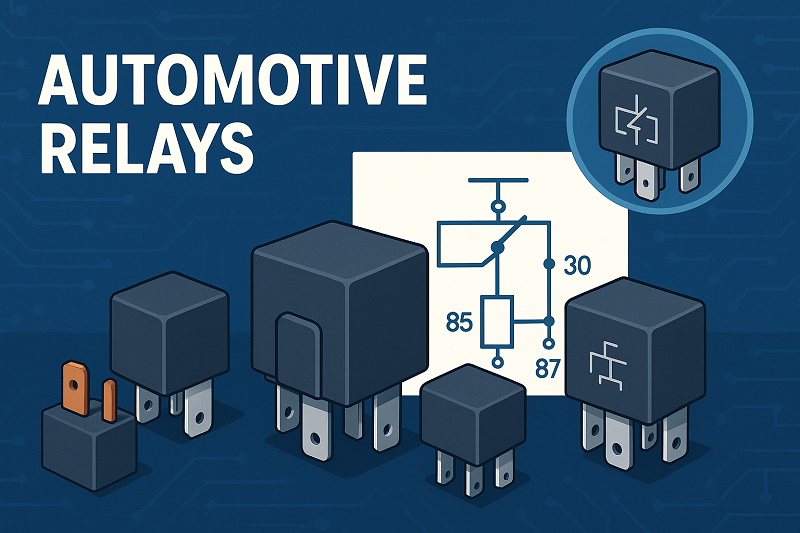
Automotive relays from TE Connectivity, Omron, Panasonic, and Denso lead the market in 2025. Choosing the right relay ensures vehicle safety, reliability, and performance. Manufacturers respond to rising demand for electric vehicles, smart features, and strict fuel efficiency rules. Key trends include slim relay designs, solid-state technology, and relays that resist shock and heat.Market leaders invest in miniaturized, high-current relays.Electric vehicles push the need for efficient relay switching.Safety standards drive innovations in relay durability and control.Market Aspect2025 Trend or LeaderLargest Market RegionAsia-PacificFastest-Growing SegmentElectric VehiclesLeading CompaniesTE Connectivity, Omron, Panasonic, DensoBest Automotive Relays 2025Cit Relay & SwitchCit Relay & Switch stands out among automotive relay manufacturers for its robust and versatile relay models. The A9 Series and A2S Series lead the lineup in 2025. The A9 Series offers a switching capacity up to 40A, low contact resistance, and a mechanical life cycle of 10 million cycles. The A2S Series features weatherproof construction, quick connect termination, and a maximum switching power of 630 watts. Both models use RoHS lead-free AgSnO2 contacts, making them environmentally friendly. These relays operate reliably in temperatures from -40°C to 85°C and withstand high shock and vibration, making them ideal for demanding automotive environments.SpecificationA9 Series Automotive RelayA2S Series Automotive RelaySwitching CapacityUp to 40AUp to 40AContact Resistance<50 mΩ<30 mΩCoil Voltage Options6VDC, 12VDC, 24VDC6VDC, 12VDC, 24VDCMax Switching Power420W630WMechanical Life Cycle10,000,000 cycles10,000,000 cyclesShock Resistance100 m/s2147 m/s2Vibration Resistance1.27 mm, 10–40 Hz1.5 mm, 10–40 HzApplicationsLamp accessoriesABS, power steering, fuel pump, cooling fan, window controlCit’s relays meet QS9000 and ISO9002 certifications, ensuring quality and reliability for automotive relays used in safety-critical systems.OmronOmron remains a global leader in automotive relays, recognized for its innovation and broad product range. The G2RV-ST and G3RV-ST series offer ultra-slim profiles starting at 6.2 mm, supporting high-density mounting in modern vehicles. Omron’s solid-state relays provide zero-crossing functionality, reducing electrical noise and extending relay life. The G9KB high-capacity PCB power relay handles up to 50A and 600VDC, making it suitable for EV charging and energy storage. Omron’s plug-in relays, ranging from 20A to 70A, control motors, heater systems, and body electronics. These models feature lightweight construction and advanced vibration resistance, ensuring reliable operation in harsh automotive environments.Omron’s focus on automation, energy efficiency, and safety keeps its relays at the forefront of the industry, especially as electric vehicles become more prevalent.TE ConnectivityTE Connectivity delivers high-performance relays designed for extreme conditions. The CII product line includes relays rated from 1A to 60A, with many models qualified for military and aerospace use. These relays feature hermetic sealing, metal housings, and balanced force designs that reduce contact bounce and arcing. TE’s relays withstand extreme shock, vibration, and temperature, making them ideal for both commercial and military vehicles. The CII mid-range relays offer size and weight savings, supporting compact automotive designs. Multiple mounting and terminal configurations allow flexible integration into various automotive systems.TE’s relays are not position sensitive, allowing installation in any orientation.Hermetically sealed models ensure long-term reliability in harsh environments.TE remains the only manufacturer qualified to P level on many military relay specifications.PanasonicPanasonic leads in slim and solid-state relay technology. Its PhotoMOS relays, used in EV battery monitoring, feature MOSFET-enabled switching, low off-state leakage current, and stable on-resistance. These relays support the growing demand for compact, efficient automotive relays in electric vehicles and advanced driver assistance systems. Panasonic’s slim relays, with profiles as thin as 5 mm, enable high-density mounting in space-constrained environments. The company’s focus on efficiency, reliability, and cost reduction drives innovation in both automotive and industrial sectors.AspectStatistic / DetailSlim relay thicknessStarting from 5 mmKey applicationEV battery monitoring, ADASProduct featureLow leakage current, stable on-resistanceMarket leadershipAmong top automotive relay manufacturersPanasonic’s relays comply with international standards and support the shift toward electrification and smart vehicle technologies.ShenlerShenler specializes in durable, shock-resistant relays for automotive and industrial use. Its relays demonstrate over 20 million operational cycles and more than 100,000 hours of operation, highlighting exceptional durability. Shenler’s compact designs fit modern vehicle architectures, while real-time LED status indicators improve operational monitoring. The relays withstand inrush currents up to 10 times the rated current for short durations, ensuring reliability during power surges. Certifications from UL, CE, TUV, and ISO9001 confirm Shenler’s commitment to quality and safety.Image Source: statics.mylandingpages.coSilent operation and instant response times (≤1 ms) make Shenler relays suitable for sensitive automotive applications.The brand’s focus on shock resistance and long lifespan supports the needs of electric and hybrid vehicles.SiemensSiemens is renowned for advanced relay systems and reliability in critical automotive and industrial applications. The SIPROTEC 6MD66 Bay Controller and 7SJ81 Overcurrent Protection Relay use advanced algorithms for fast, accurate fault detection and isolation. These relays feature scalable, modular architectures and robust construction, ensuring reliable operation in harsh environments. Siemens relays integrate seamlessly with smart grid and automation systems, supporting future-proof vehicle and infrastructure designs.Siemens relays comply with international standards (IEC, IEEE) and offer remote diagnostics and predictive maintenance.Their use in substation automation, renewable energy, and transportation grids demonstrates versatility and reliability.Siemens’ commitment to innovation and safety makes its relays a preferred choice for critical automotive and power applications.DensoDenso holds a leading position in the automotive relay market, especially for electric vehicles. The company invests heavily in research and development to enhance relay durability, compactness, and compliance with global safety standards. Denso’s relays use advanced technologies such as gas-filled contact chambers, magnetic blowouts, and hermetically sealed casings. These features improve performance under high voltage and current, meeting the demands of modern EVs. Silver contacts provide high electrical conductivity and thermal stability, supporting efficient operation and long service life.Denso relays handle voltages above 400V and currents above 200A, essential for EV powertrains.Strategic collaborations with OEMs accelerate the development of specialized high-voltage relay solutions.Denso’s focus on efficiency, safety, and innovation ensures its relays remain at the forefront of the automotive relays market.HELLAHELLA is recognized for high-performance relays used in safety, lighting, and smart vehicle systems. The brand invests in smart relay systems for automated and connected vehicles, supporting advanced driver assistance and electrification trends. HELLA relays offer robust construction, high switching capacities, and compliance with global safety standards. The company’s focus on innovation and reliability makes its relays suitable for both traditional and electric vehicles.Leading CompaniesKey Performance and Market FocusDENSO CorporationHigh-performance relays, solid-state technology, global partnershipsHELLA GmbH & Co.Safety, lighting, smart relay systems, automationHELLA’s relays support the growing integration of electronics and safety features in modern vehicles, reinforcing its reputation among top automotive relay manufacturers.Leading Automotive Relay ManufacturersNorth AmericaNorth America remains a powerhouse in the automotive relay industry. The United States and Canada lead the region, with Detroit serving as a major automotive hub. Manufacturers in this area focus on advanced vehicle electronics, strict safety regulations, and energy efficiency. The market features both power relays for high-current switching and signal relays for low-power control.AspectDetailsMarket RegionNorth America, primarily United States and CanadaMarket DriversIncreasing vehicle electronics complexity, safety regulations, energy efficiency demandsKey Market SegmentsPower Relays (high-current switching for lighting, powertrain), Signal Relays (low-power control signals)Major PlayersOmron Corporation, Panasonic Corporation, TE Connectivity, Fujitsu, Delphi TechnologiesU.S. Market CharacteristicsLargest and most mature market; established automotive hubs (e.g., Detroit); strong regulatory environmentCanada Market CharacteristicsSmaller but growing; focus on advanced manufacturing and eco-friendly vehiclesMarket Growth FactorsTechnological advancements, regulatory compliance, collaboration among manufacturers and tech providersFuture Demand DriversAdvanced driver assistance systems, hybrid/electric vehicles, sustainability initiativesCompetitive LandscapeConcentrated with major global and specialized players; ongoing innovation and partnershipsManufacturers in North America often lead in customization and advanced features. They respond quickly to new safety standards and collaborate with technology providers. The region’s brands consistently appear in global rankings due to their focus on quality and innovation.Global MarketGlobally, automotive relay manufacturers compete in a fast-changing environment. TE Connectivity, Omron, and Denso hold top positions in worldwide rankings. These brands invest heavily in research and development, focusing on electric vehicles, smart mobility, and advanced driver assistance systems.AspectEvidence SummaryLeading CompaniesTE Connectivity, Omron Corporation, Denso Corporation dominate through broad portfolios, innovation, and quality.Market PositioningMarket share and sales volume analyzed for 200+ companies globally and regionally.Innovation & TechnologyFocus on advanced relay solutions for EVs, ADAS, and smart mobility; continuous R&D emphasized.Competitive EnvironmentIntense competition with rapid technological evolution and strategic collaborations to maintain/grow market share.Regional DominanceEast Asia leads due to strong automotive manufacturing hubs and EV adoption; South Asia and Oceania growing fast.Market DriversGrowth in electric vehicles, ADAS, passenger comfort, and fuel efficiency regulations drive demand.ChallengesRising manufacturing costs, stringent safety regulations, and counterfeit relay risks impact competitiveness.Market Research MethodologyData sourced from financial reports, regulatory bodies, expert consultations, and statistical tools for accuracy.East Asia dominates the global market, driven by strong automotive manufacturing and rapid electric vehicle adoption. Brands from this region often top industry rankings. The market also sees fast growth in South Asia and Oceania. Manufacturers worldwide face challenges such as rising costs and strict regulations. They rely on accurate data and strategic partnerships to stay ahead. Customization, advanced features, and innovation remain key trends shaping the future of automotive relay brands.Key Features of Automotive RelaysPerformanceAutomotive relays must deliver reliable performance in a wide range of automotive applications. Engineers look for relays that handle complex electrical loads and support high current capacity. Compatibility with different vehicle electrical systems ensures seamless integration. Many modern relays now include advanced diagnostic features, such as fault detection and real-time status indicators. These features help technicians identify issues quickly and keep vehicles running smoothly.Reliability and durability remain critical for relay selection.User-friendly interfaces, like touchscreens or voice commands, improve relay testing efficiency.Integration with electric vehicles, ADAS, and autonomous driving systems is now standard in many automotive applications.Environmental resistance and compliance with industry standards guarantee relay quality and safety.Performance testing often includes visual inspection, continuity checks, and mechanical operation tests. Technicians use relay testers to simulate real-world conditions and verify that relays meet the demands of modern vehicles.DurabilityDurability defines how well a relay withstands harsh automotive environments. Manufacturers test relays for shock, vibration, and extreme temperatures to ensure long service life. The table below highlights key durability metrics for relays used in automotive applications:MetricStandard ModelsHigh Performance ModelsMechanical Life Expectancy10 million operations10 million operationsOperating Temperature Range-55°C to +85°C-65°C to +125°CVibration Resistance10G30GShock Resistance30G100GRelays with AEC-Q101 certification and robust thermal management show high reliability by powertrain. Features like hermetic sealing and advanced contact materials protect against corrosion and wear. These qualities ensure reliable performance even in the most demanding automotive applications.ApplicationsRelays serve a wide range of automotive applications, from passenger cars to heavy commercial vehicles. The table below shows how relay use varies by segment:CategorySegmentKey InsightsVehicle TypePassenger CarsPCB relays control lighting, engine, infotainment.Heavy Commercial VehiclesHigh current capacity relays support logistics and transportation needs.Propulsion SystemPowertrainRelays manage engine and drivetrain control.Electric & HybridSolid-state and high voltage relays meet lightweight, high-performance needs.ApplicationBody and ChassisRelays operate lighting, locks, and body electronics.Safety & SecuritySpecialized relays protect critical systems.Relays with high current capacity play a vital role in powertrain and safety systems. The growing use of electric vehicles increases demand for advanced relay solutions. Manufacturers focus on quality and reliability by powertrain to meet the needs of modern automotive applications.Automotive Relays Comparison TableSelecting the right relay for automotive applications requires a close look at technical specifications, unique features, and practical advantages. The table below compares leading relay models from top manufacturers, highlighting their suitability for different automotive needs.Model/BrandTypeSpecs & FeaturesApplicationsProsConsUnique FeaturesOmron G9KBSolid-State50A, 600VDC, ultra-slim, zero-crossing switchingEV charging, powertrainFast response, compactHigher costZero-crossing, slim designTE Connectivity CIIElectromechanical1A–60A, hermetic seal, metal housingSafety, military vehiclesHigh durability, versatileBulkyHermetic, position-insensitivePanasonic PhotoMOSSolid-StateMOSFET, low leakage, 5mm thicknessBattery monitoring, ADASSilent, energy efficientLimited current capacityStable on-resistanceDenso High VoltageElectromechanical400V+, 200A+, gas-filled contactsEV powertrainsHandles high voltage/currentLarger sizeMagnetic blowout, sealedHELLA Smart RelayDigitalMicroprocessor-based, programmable, LED indicatorLighting, safety systemsProgrammable, visual statusNeeds auxiliary supplySCADA compatibleShenler CompactElectromechanical20M cycles, LED status, shock-resistantHybrid vehicles, controlsLong lifespan, silentFewer programming optionsReal-time LED monitoringNote: Automotive relays often follow DIN 72552 terminal numbering, which helps technicians identify coil and contact pins easily. Many relays now include built-in diodes to protect circuits from voltage spikes, especially in sensitive automotive applications.Electromechanical relays use mechanical force to switch circuits. They offer high reliability but require more maintenance.Solid-state relays use transistors or MOSFETs. They respond quickly and resist vibration, making them ideal for modern automotive applications.Digital and programmable relays provide advanced features like self-monitoring, visual indication, and compatibility with vehicle automation systems.Choosing the right relay depends on the required current, voltage, and the specific automotive application. Compact relays with high shock resistance work best for electric vehicles and advanced driver assistance systems. Models with programmable features and visual indicators support smart vehicle integration.Consumer Reports and ReliabilityUser FeedbackConsumer reports play a crucial role in shaping the automotive industry. Drivers and technicians often share their experiences with relay performance, highlighting both strengths and weaknesses. Many users report that vehicles equipped with relays from leading manufacturers, such as TE Connectivity and Omron, show fewer electrical failures. These brands receive high ratings for durability and consistent operation in harsh conditions. Consumer reports reliability rankings often mention the importance of advanced relay systems in electric vehicles and cars with automated features.A growing number of consumers demand vehicles with the best reliability. They look for models that use high-quality relays to support power windows, lighting, and infotainment. Data from recent surveys show that relay-related issues have decreased in vehicles using solid-state and shock-resistant relays. This trend reflects the impact of innovation on car brand reliability.AspectDetailsMarket Size (2023)USD 14.8 billionProjected Market Size (2024-2032)Growth from USD 15.82 billion in 2024 to USD 26.98 billion by 2032, CAGR 6.9%Largest SegmentPassenger CarsFastest Growth SegmentElectric VehiclesGrowth DriversIncreasing EV adoption, ADAS advancements, demand for reliable relaysRelay ApplicationsPowertrain, communications, safety, infotainmentIndustry TrendsMore relays per vehicle for safety and electronicsMost Reliable Car BrandsMost reliable car brands consistently earn top rankings in consumer reports. These brands invest in advanced relay technologies to achieve the best reliability. For example, automakers in China and the United States lead the market by integrating high-performance relays into electric and passenger vehicles. Data shows that brands using relays from trusted suppliers experience fewer warranty claims and higher reliability ratings.Evidence AspectSupporting DetailsEV Sales Growth (2023)Nearly 14 million units sold; EV share rose from 4% (2020) to 18% (2023)Leading Market CountryChina with 10.1 million EV sales in 2024ADAS Market ProjectionUSD 42.9 billion by 2024; CAGR 17.8% (2025-2034)Consumer Demand DriversComfort, safety, connectivity requiring multiple relays for power windows, lighting, infotainmentProduct InnovationsNew relay components for EVs (e.g., Durakool DG82M, DE40, DHVC300)Relay choice directly affects car brand reliability and reputation. Brands that prioritize reliable relay systems often receive higher reliability ratings and better rankings in consumer reports. As the market grows, automakers continue to focus on relay quality to maintain their position among the most reliable car brands.How to Choose Automotive RelaysApplication MatchSelecting the right relay starts with understanding the needs of modern vehicles. Engineers look for relays that can handle higher voltages and currents, especially as electric and hybrid vehicles become more common. Advanced Driver-Assistance Systems (ADAS) add more electronics, so relays must be reliable and able to manage complex circuits. Miniaturization trends push for smaller, multifunctional relay components that fit into tight spaces. Solid-state relays now compete with traditional types because they last longer and need less maintenance. Safety and emission rules also shape relay design, making it important to choose relays that meet strict standards. For example, Toshiba’s TLX9910 photocoupler works well in high-voltage systems and supports miniaturization, helping vehicles stay safe and efficient.Tip: Always match the relay’s voltage, current, and switching speed to the specific application in the vehicle.Quality StandardsHigh-quality products stand out by meeting international standards and passing strict tests. Automated relay testing systems use advanced hardware and software to check for faults and ensure each relay works as expected. These systems help reduce errors and make testing faster and more reliable. Standards like IEC 60947-4-1 and IEC 61810 set the rules for electromagnetic compatibility, durability, and load-bearing. Manufacturers use materials such as silver alloys and ceramics to improve contact resistance and thermal stability. Many relays now include smart features like CANBus compatibility and IoT diagnostics, which help monitor relay health and predict failures. Certifications like UL and CE show that relays meet safety and environmental rules, giving buyers confidence in the quality of high-quality products.Automated testing improves reliability and ensures every relay meets industry standards.Smart technology integration allows for better monitoring and maintenance in vehicles.CustomizationCustomization lets automakers and engineers choose relays that fit unique vehicle needs. Manufacturers offer different pole-throw configurations, mounting options, and special features. For example, multi-throw relays help with complex circuit routing, while compact PCB-mount relays save space. Strategic partnerships between relay makers and car companies lead to custom modules for electric vehicles and ADAS. Automation in manufacturing helps lower costs and makes it easier to create custom designs. Regional assembly hubs and strict safety rules also drive customization, ensuring relays meet local needs and regulations.Customization AspectMarket Demand and Innovation ExamplePole-Throw ConfigurationsMulti-throw relays for complex circuits; simple formats for small spacesMounting OptionsChassis, DIN-rail, panel, and PCB-mount for different vehicle designsStrategic PartnershipsOEM collaborations for custom relay modules in EVs and ADASManufacturing InnovationsAutomation and lean processes for better yield and lower costsR&D FocusMiniaturization, high-speed switching, and sustainabilityChoosing the right relay means looking at application needs, quality standards, and available customization. This approach helps ensure vehicles use reliable, high-quality products that support safety and performance.Automotive relays from brands like Omron, TE Connectivity, Panasonic, and Denso meet the needs of electric vehicles, compact cars, and heavy-duty applications.Rapid EV adoption and advanced electronics drive demand for high-voltage, reliable relays.Reliability tests and performance evaluations highlight models that excel in durability and innovation.Selecting relays that match vehicle requirements ensures reliability for 2025 and supports safe, efficient automotive systems.FAQWhat is the primary function of an automotive relay?Automotive relays switch electrical circuits on and off, enabling efficient control of high-current devices like headlights, fuel pumps, and cooling fans. They protect sensitive electronics by isolating low-power control signals from high-power loads.How do solid-state relays differ from electromechanical relays?Solid-state relays use semiconductors for switching, offering faster response times and higher vibration resistance. Electromechanical relays rely on physical contacts, providing higher current capacity but requiring more maintenance.Tip: Solid-state relays are ideal for electric vehicles due to their durability and compact design.Which certifications should automotive relays meet?Automotive relays should comply with standards like AEC-Q101, UL, and ISO9001. These certifications ensure reliability, safety, and environmental compatibility in demanding automotive applications.Can automotive relays be customized for specific vehicles?Manufacturers offer customization options, including pole-throw configurations, mounting styles, and advanced features like LED indicators. Custom relays meet unique requirements for electric vehicles, ADAS, and compact designs.What factors influence relay durability?Durability depends on materials, sealing, and design. Features like hermetic sealing, silver contacts, and shock resistance improve lifespan. Relays with certifications like IEC 61810 withstand harsh conditions and ensure long-term reliability.Note: Always check operating temperature and mechanical life cycle when evaluating relay durability.
On 2025-07-10


