 info@kynix.com
 00852-6915 1330


 0
0


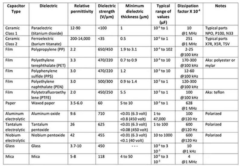
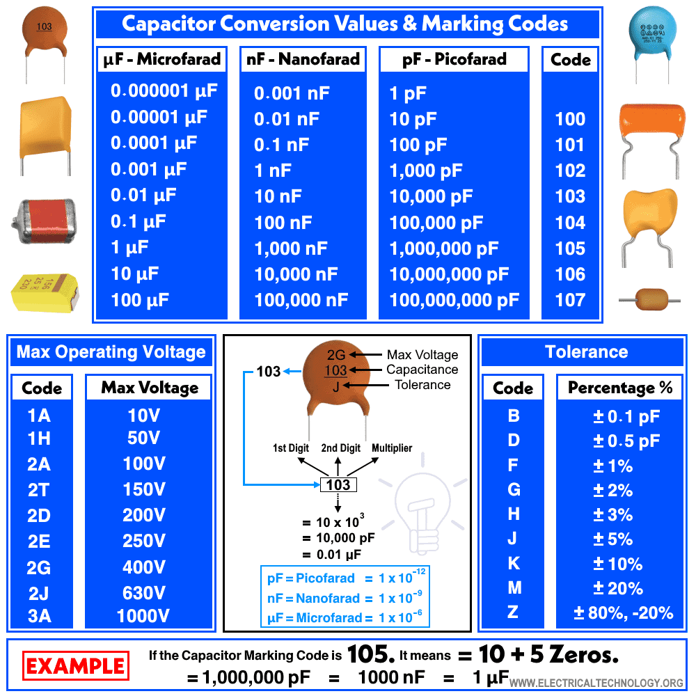

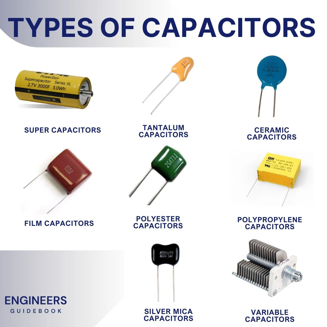
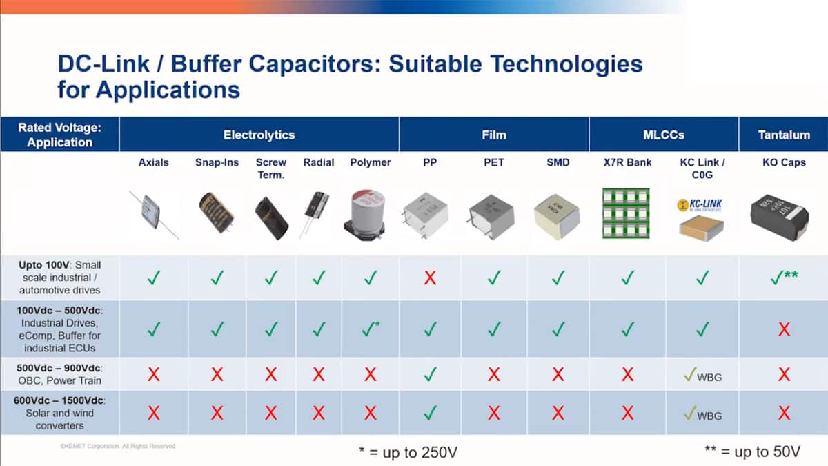
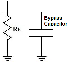
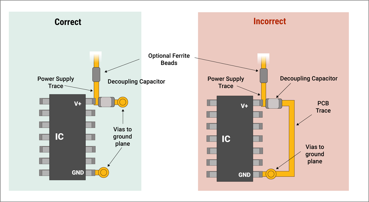
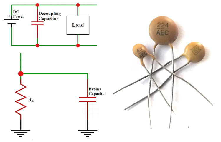
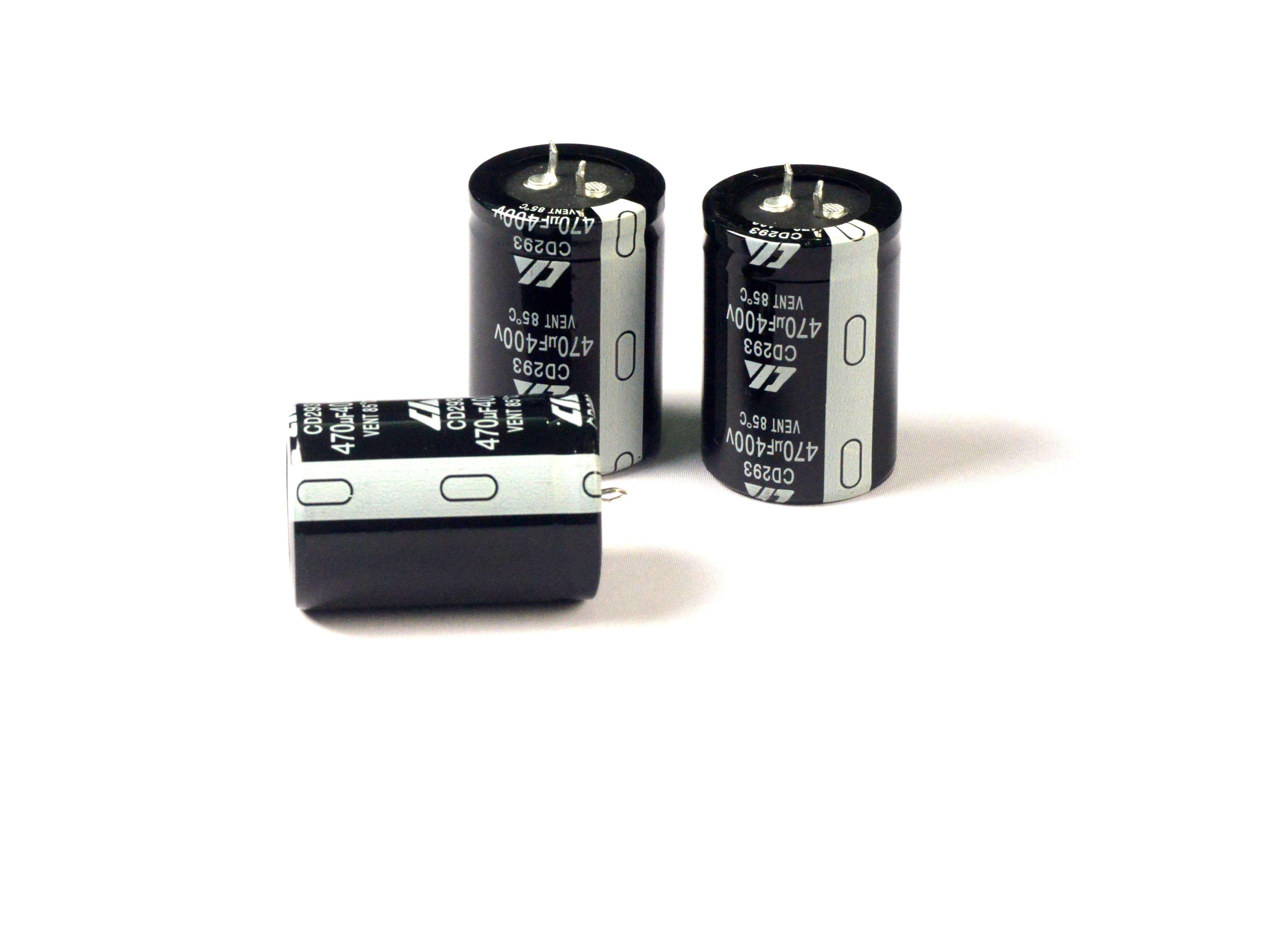
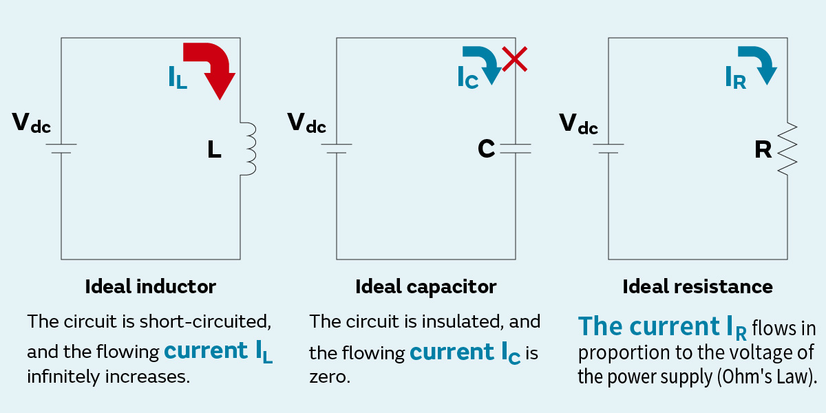


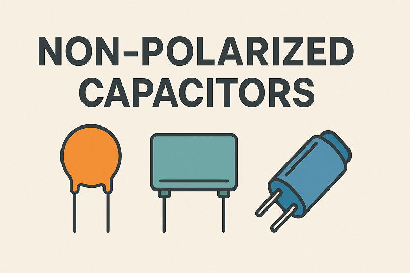
IntroductionAre you an engineer or electronics enthusiast who has ever found yourself scratching your head, wondering how to choose a capacitor for your latest project? You're not alone. The world of capacitors can be daunting, with a myriad of types, specifications, and applications. Choosing the right capacitor is not just about matching capacitance values; it's about understanding the nuances that can make or break your circuit's performance, reliability, and even its cost-effectiveness. In fact, a recent survey revealed that over 60% of circuit design failures are directly or indirectly linked to improper component selection, with capacitors being a leading culprit. This comprehensive guide aims to demystify the process, providing you with the ultimate handbook for selecting the perfect capacitor every time. We'll delve into core principles, explore various types, and equip you with the knowledge to make informed decisions.How to Choose a Capacitor: Core Principles and ProcessSelecting the ideal capacitor involves a systematic approach, considering various parameters beyond just capacitance. It’s a delicate balance between electrical performance, transient response, and practical considerations like PCB area and cost. Here’s a streamlined process to guide your selection:The Capacitor Selection ChecklistApplication Requirements: What is the primary function of the capacitor in your circuit? Is it for filtering, decoupling, energy storage, timing, or coupling? Each application demands specific characteristics.Capacitance Value: Determine the required capacitance based on circuit calculations. This is often the starting point, but rarely the only factor.Voltage Rating: The capacitor’s voltage rating must be significantly higher than the maximum operating voltage of your circuit, typically with a safety margin (e.g., 1.5x to 2x). Over-voltage can lead to catastrophic failure.Tolerance: How precise does the capacitance need to be? Some applications require tight tolerances, while others can tolerate wider variations.Equivalent Series Resistance (ESR) and Equivalent Series Inductance (ESL): These parasitic elements are crucial, especially in high-frequency or power supply applications. Low ESR and ESL are often desirable for efficient operation and ripple reduction.Ripple Current Rating: For power supply filtering, the capacitor must be able to handle the ripple current without excessive heating, which can degrade its lifespan.Temperature Characteristics: How does the capacitance change with temperature? Different dielectric materials exhibit varying temperature stability. Consider the operating temperature range of your application.Frequency Response: The capacitor’s impedance changes with frequency. Ensure it performs optimally at your circuit’s operating frequencies.Size and Package: Physical dimensions and mounting style (through-hole, surface mount) are critical for PCB layout and space constraints.Cost: While performance is paramount, cost-effectiveness is always a consideration in mass production.Reliability and Lifetime: For critical applications, consider the expected lifespan and failure rates of different capacitor types.A Step-by-Step Selection FlowDefine the Role: Clearly identify the capacitor’s function (e.g., input filter, output smoothing, signal coupling, timing). This immediately narrows down the possible types.Calculate Core Values: Determine the nominal capacitance and minimum voltage rating based on circuit design equations.Consider Environmental Factors: Account for operating temperature range, humidity, and potential mechanical stresses.Analyze AC Characteristics: Evaluate ESR, ESL, and impedance at relevant frequencies, especially for high-frequency or switching applications.Assess Reliability Needs: For long-life or high-reliability systems, prioritize components with proven track records and appropriate derating guidelines.Evaluate Physical Constraints: Check available PCB space, height restrictions, and mounting preferences.Compare Candidate Types: Based on the above, compare different capacitor technologies (ceramic, electrolytic, tantalum, film) against your specific requirements.Prototype and Test: Always validate your selection through prototyping and rigorous testing under actual operating conditions. This is where theoretical choices meet real-world performance."The art of capacitor selection lies not just in knowing the formulas, but in understanding the subtle interplay between electrical parameters and real-world application demands," notes a seasoned electronics engineer. This holistic approach ensures optimal circuit performance and longevity.Understanding Capacitor Codes and Specifications (Capacitor Codes Explained)Capacitors, especially smaller ones, often don't have their full capacitance value printed on them. Instead, they use a system of codes that can sometimes be a puzzle. Deciphering these codes is a fundamental skill for any engineer. Let's break down the common coding schemes:Numeric Codes (EIA Standard)Many ceramic and film capacitors use a three-digit numeric code. The first two digits represent the significant figures of the capacitance value, and the third digit is the multiplier (number of zeros). The unit is typically picofarads (pF).CodeCapacitance Value (pF)Example10010 pF10 with 0 zeros = 10 pF101100 pF10 with 1 zero = 100 pF1021,000 pF (1 nF)10 with 2 zeros = 1,000 pF10310,000 pF (10 nF)10 with 3 zeros = 10,000 pF104100,000 pF (100 nF)10 with 4 zeros = 100,000 pF224220,000 pF (220 nF)22 with 4 zeros = 220,000 pFSometimes, a letter follows the numeric code, indicating the tolerance of the capacitor. Common tolerance codes include:F: ±1%G: ±2%J: ±5%K: ±10%M: ±20%So, a capacitor marked 104K means 100,000 pF (or 0.1 µF) with a ±10% tolerance. This is a crucial detail, as a capacitor's actual value can vary within this range, impacting circuit performance.Color CodesWhile less common on modern components, some older or specialized capacitors (like mica or polyester film) might use color bands, similar to resistors. Each color corresponds to a number, and the sequence of bands indicates capacitance, tolerance, and sometimes voltage. If you encounter these, a quick reference to a capacitor color code chart is invaluable. I once spent hours debugging a vintage radio, only to find a misread color-coded capacitor was the culprit! Always double-check.Voltage RatingsCapacitors also have a voltage rating, which is the maximum DC voltage they can safely withstand. This is usually printed directly on the component, often in volts (V) or kilovolts (kV). For electrolytic capacitors, this is particularly important, as exceeding the voltage rating can lead to catastrophic failure, including explosion. Always select a capacitor with a voltage rating significantly higher than your circuit's maximum operating voltage, typically 1.5 to 2 times the expected voltage.Other MarkingsPolarity: Electrolytic and tantalum capacitors are polarized, meaning they must be installed in a specific orientation (positive to positive, negative to negative). They will have markings (e.g., a stripe, a minus sign, or a longer lead for positive) to indicate polarity. Non-polarized capacitors (like ceramic or film) can be installed in either direction.Temperature Coefficient: Some capacitors, especially ceramic types, might have a code indicating how their capacitance changes with temperature (e.g., NPO, X7R, Z5U). This is vital for applications requiring stable performance across varying temperatures.Date Codes/Manufacturer Logos: These provide information about the manufacturing batch and origin, useful for traceability.SMD Capacitor Sizes and Codes Explained (SMD Capacitor Sizes and Codes)Surface Mount Device (SMD) capacitors are ubiquitous in modern electronics due to their small size and suitability for automated assembly. Unlike their through-hole counterparts, SMD capacitors are typically marked with a two or three-digit code indicating their physical dimensions, rather than their capacitance. The actual capacitance value is often too small to be legibly printed on the tiny component, or it might be indicated by a single letter or a very small numeric code, which still requires a lookup table.Common SMD Package SizesSMD capacitor sizes are standardized by the Electronic Industries Alliance (EIA) and are typically expressed in imperial (inches) or metric (millimeters) units. The most common sizes you'll encounter are:Imperial Size (inches)Metric Size (mm)Typical Applications02010603Miniaturized devices, wearables, smartphones04021005Smartphones, tablets, compact modules06031608General purpose, consumer electronics08052012General purpose, power supplies, industrial12063216Power filtering, higher voltage applications12103225Power filtering, higher capacitance needs18124532High power, automotive, industrial22205650High power, industrial, specialized applicationsChoosing the right SMD size is a trade-off between component cost, available PCB space, and electrical performance. Smaller components generally have lower parasitic inductance (ESL), which is beneficial for high-frequency applications, but they can be more challenging to handle during assembly and may have lower voltage or capacitance ratings. Larger sizes offer higher capacitance and voltage ratings but occupy more board space.SMD Capacitor MarkingsAs mentioned, direct capacitance values are rare on SMD capacitors. Instead, you might find:No Marking: Many small SMD ceramic capacitors have no markings at all. Their value is determined by their position on the Bill of Materials (BOM) and the PCB design.Single Letter Code: Some manufacturers use a single letter code (e.g., 'A', 'B', 'C') to denote capacitance, which requires referring to the manufacturer's datasheet.Three-Digit Code (similar to through-hole): Larger SMD capacitors, especially electrolytic or tantalum types, might use the same three-digit code as through-hole components (e.g., 104 for 100nF).Voltage and Tolerance Markings: These are sometimes present, especially on larger SMD capacitors, using standard numeric or alphanumeric codes.Professional Tip: When working with unmarked SMD components, always rely on your Bill of Materials (BOM) and schematic. If in doubt, measure the capacitance with a suitable LCR meter. This prevents costly errors and ensures circuit integrity.The Critical Role of Capacitor ESR (Capacitor ESR and its Importance)Beyond capacitance and voltage, two often-overlooked but critically important parasitic parameters of a capacitor are its Equivalent Series Resistance (ESR) and Equivalent Series Inductance (ESL). While an ideal capacitor would have zero resistance and inductance, real-world capacitors are far from ideal. Understanding and accounting for ESR and ESL is paramount, especially in high-frequency applications, power supplies, and any circuit where efficiency and thermal management are concerns.What is ESR?Equivalent Series Resistance (ESR) is the total resistance in series with an ideal capacitor. It represents the sum of all resistive losses within the capacitor, including the resistance of the leads, the dielectric material, and the electrode plates. When current flows through a capacitor, the ESR causes a voltage drop and generates heat (I²R losses). This heat can significantly impact the capacitor’s lifespan and overall circuit efficiency.Why is ESR Important?Heat Generation and Lifespan: High ESR leads to increased power dissipation and heat generation within the capacitor. For every watt of power dissipated, the capacitor’s internal temperature rises. This elevated temperature accelerates the degradation of the dielectric material, especially in electrolytic capacitors, drastically reducing their lifespan. A general rule of thumb is that for every 10°C increase in operating temperature, the lifespan of an electrolytic capacitor is halved.Ripple Voltage: In power supply filtering applications, capacitors are used to smooth out ripple voltage. A higher ESR means a larger voltage drop across the capacitor, resulting in increased ripple voltage at the output. This can lead to instability and noise in sensitive circuits. Imagine trying to fill a leaky bucket; the higher the ESR, the bigger the leak.Efficiency: In switching power supplies (e.g., buck, boost converters), capacitors are constantly charging and discharging. The energy lost due to ESR directly reduces the efficiency of the power converter. Lower ESR capacitors are essential for achieving high efficiency in these designs.Resonance and Stability: ESR affects the impedance characteristics of a capacitor across different frequencies. At high frequencies, a capacitor can become inductive due to ESL, and the ESR determines the damping of this resonance. Proper ESR values are crucial for maintaining circuit stability and preventing unwanted oscillations.ESR Measurement and ConsiderationsESR is not a static value; it varies with frequency, temperature, and age. Manufacturers typically specify ESR at a particular frequency (e.g., 100 kHz or 120 Hz) and temperature. When selecting a capacitor, always check the datasheet for ESR specifications relevant to your operating conditions.Capacitor TypeTypical ESR CharacteristicsBest Use CasesElectrolytic (Aluminum)Moderate to High ESR, varies significantly with temperature and frequency.Power supply filtering, energy storage, low-frequency applications.TantalumLow to Moderate ESR, more stable with temperature than aluminum electrolytics.Decoupling, filtering in compact designs, moderate frequency.Ceramic (MLCC)Very Low ESR, excellent high-frequency performance, stable with temperature (depending on dielectric).High-frequency decoupling, resonant circuits, small form factor.FilmVery Low ESR, excellent stability, good for AC applications.Audio coupling, precision timing, high-voltage applications.Important Note: While low ESR is generally desirable, especially for power applications, it’s not always the sole criterion. For instance, in some resonant circuits, a specific ESR value might be required for proper damping. Always consider the overall circuit requirements.[Image: A graph comparing the ESR characteristics of different capacitor types across frequency.]Capacitor Types and Application Scenarios Explained (Capacitor Types and Applications)The vast world of capacitors can be broadly categorized by their dielectric material, which largely dictates their characteristics and suitability for different applications. Understanding these types is fundamental to making informed selection decisions.[Image: A visual gallery showcasing various types of capacitors, highlighting their diverse forms and applications.]Electrolytic Capacitors (Electrolytic Capacitor Selection Guide)Electrolytic capacitors are known for offering high capacitance values in a relatively small package. They use an electrolyte (liquid or solid) as one of their plates, which allows for a very thin dielectric layer and thus high capacitance. They are almost always polarized, meaning they must be connected with the correct polarity (positive to positive, negative to negative).Key Characteristics:High Capacitance: Ranging from microfarads (µF) to farads (F).Polarized: Incorrect polarity can lead to damage or explosion.Higher ESR/ESL: Compared to ceramic or film capacitors, they generally have higher ESR and ESL, especially at high frequencies.Temperature Sensitivity: Performance and lifespan are significantly affected by temperature.Limited Lifespan: Due to the electrolyte, they have a finite lifespan, which is reduced by heat and ripple current.Applications:Power Supply Filtering: Their high capacitance makes them ideal for smoothing rectified AC voltage into stable DC voltage in power supplies.Coupling and Decoupling: Used to block DC while allowing AC signals to pass, or to stabilize voltage rails by shunting high-frequency noise to ground.Energy Storage: In applications requiring bursts of power, such as camera flashes or audio amplifiers.Timing Circuits: In low-frequency timing applications where large capacitance is needed.Selection Considerations:Ripple Current Rating: Crucial for power supply applications. Ensure the capacitor can handle the expected ripple current without overheating.Operating Temperature: Select a capacitor rated for the maximum expected ambient temperature, and consider derating for extended life.Lifespan: Factor in the expected lifespan under operating conditions. High-quality electrolytics offer longer life.Size: They can be bulky, so physical space is a consideration.Decision Tree for Electrolytic Capacitors:Is the application polarized? (Yes/No) - If no, consider other types.Is high capacitance (µF to mF) required? (Yes/No) - If no, other types might be better.What is the maximum ripple current? - Select a capacitor with a ripple current rating at least 1.5x the expected value.What is the maximum operating temperature? - Choose a capacitor with an appropriate temperature rating.What is the desired lifespan? - Higher quality and lower ESR electrolytics offer longer life.Ceramic Capacitors (Ceramic Capacitor Selection Guide)Ceramic capacitors are perhaps the most widely used type due to their small size, low cost, and excellent high-frequency performance. They use a ceramic material as the dielectric and are non-polarized.Key Characteristics:Small Size: Available in very small SMD packages.Low ESR/ESL: Excellent for high-frequency applications and decoupling.Non-Polarized: Can be installed in any orientation.Wide Capacitance Range: From picofarads (pF) to several microfarads (µF).Temperature Stability: Varies significantly with dielectric type (e.g., NPO/COG for high stability, X7R for general purpose, Z5U/Y5V for high capacitance but poor stability).Voltage Coefficient: Capacitance can decrease significantly with applied DC voltage, especially for high-K dielectrics like X7R.Applications:Decoupling and Bypass: Essential for filtering noise and stabilizing voltage rails in digital and analog circuits.High-Frequency Filtering: Due to their low ESR/ESL, they are excellent for RF circuits and high-speed data lines.Resonant Circuits: In oscillators and tuned circuits.Timing Circuits: In applications requiring precise timing and stability (NPO/COG types).Selection Considerations:Dielectric Type: Choose based on temperature stability and voltage coefficient requirements.Voltage Rating: Be aware of capacitance degradation under DC bias for certain dielectrics.Size: Select the smallest size that meets electrical and mechanical requirements.Microphonics: Some ceramic capacitors can exhibit piezoelectric effects, generating noise when subjected to mechanical vibration.Decision Tree for Ceramic Capacitors:Is the application high-frequency or decoupling? (Yes/No) - If yes, ceramic is a strong candidate.What level of temperature stability is required? (High/Medium/Low) - NPO/COG for high, X7R for medium, Z5U/Y5V for low.What is the maximum DC voltage? - Account for voltage coefficient, especially for X7R and similar types.Is physical size critical? - Ceramic offers the smallest footprints.Tantalum Capacitors (Tantalum Capacitor Advantages and Disadvantages)Tantalum capacitors are a type of electrolytic capacitor that use tantalum pentoxide as the dielectric. They offer a good balance of high capacitance, small size, and relatively low ESR compared to aluminum electrolytics. They are polarized.Advantages:High Volumetric Efficiency: More capacitance per unit volume than aluminum electrolytics.Lower ESR: Generally lower ESR than aluminum electrolytics, leading to better ripple handling and efficiency.Stable Performance: More stable capacitance and ESR over temperature and frequency than aluminum electrolytics.Long Lifespan: Solid tantalum capacitors have a very long lifespan if operated within their ratings.Disadvantages:Catastrophic Failure Mode: Can fail short circuit if subjected to overvoltage, reverse voltage, or excessive ripple current, potentially leading to thermal runaway and fire. This is a critical safety concern.Higher Cost: Generally more expensive than aluminum electrolytic or ceramic capacitors for similar capacitance values.Polarized: Requires correct installation.Sensitivity to Surge Current: Can be damaged by high inrush currents.Applications:Decoupling and Filtering: In compact power supplies and digital circuits where space is limited and stable performance is required.Medical Devices: Where reliability and small size are paramount.Automotive Electronics: Due to their robust performance over temperature.Selection Considerations:Voltage Derating: Always apply significant voltage derating (e.g., 50% or more) to prevent catastrophic failures, especially in high-impedance circuits or those with voltage transients.Surge Current: Consider inrush current limiting if the application involves high surge currents.Cost vs. Performance: Weigh the benefits of their performance against their higher cost and potential failure mode.Film Capacitors for Audio Applications (Film Capacitor for Audio Applications)Film capacitors use a plastic film (e.g., polyester, polypropylene, polystyrene) as the dielectric. They are known for their excellent stability, low distortion, and very low ESR/ESL, making them ideal for precision applications, especially in audio.Key Characteristics:Excellent Stability: Capacitance changes very little with temperature, voltage, or time.Very Low ESR/ESL: Ideal for high-frequency and precision applications.Low Dielectric Absorption: Important for timing and sample-and-hold circuits.Non-Polarized: Can be installed in any direction.Good Pulse Handling: Can withstand high current pulses.Larger Size: Generally larger than ceramic or tantalum capacitors for the same capacitance.Applications:Audio Coupling and Decoupling: Their low distortion and excellent frequency response make them a favorite in high-fidelity audio equipment.Precision Timing Circuits: In oscillators and filters where stability is critical.Snubber Circuits: To suppress voltage spikes in power electronics.AC Applications: Motor run capacitors, power factor correction.Case Study: Enhancing Audio Quality with Film CapacitorsIn a high-end audio amplifier design, the choice of coupling capacitors between stages significantly impacts sound quality. Replacing standard electrolytic capacitors with high-quality polypropylene film capacitors can dramatically reduce distortion and improve transient response, leading to a cleaner, more detailed sound. The film capacitor’s superior linearity and low dielectric absorption ensure that the audio signal remains faithful to the original, without introducing unwanted artifacts. This is where the subtle art of component selection truly shines, transforming a good circuit into a great one.[Image: A selection of film capacitors, often used in high-fidelity audio equipment for their low distortion characteristics.]Capacitor Voltage Rating GuideThe voltage rating of a capacitor is a critical parameter that defines the maximum continuous DC voltage that can be applied across its terminals without causing damage or premature failure. Exceeding this rating, even momentarily, can lead to irreversible damage, including dielectric breakdown, short circuits, or even explosive failure, especially in electrolytic capacitors. Therefore, understanding and correctly applying voltage ratings is paramount for circuit reliability and safety.Understanding Voltage RatingsCapacitor voltage ratings are typically specified as DC Working Voltage (WVDC) or Rated Voltage (VR). It's important to note that these ratings are usually given at a specific temperature (often 20°C or 25°C) and may need to be derated for higher operating temperatures.The Importance of Voltage DeratingWhile it might seem intuitive to simply choose a capacitor with a voltage rating equal to or slightly above your circuit's operating voltage, this is a common pitfall. Voltage derating is the practice of selecting a capacitor with a rated voltage significantly higher than the maximum expected operating voltage. This provides a safety margin against voltage transients, spikes, and long-term degradation, thereby extending the capacitor's lifespan and improving overall circuit reliability.General Derating Guidelines:General Purpose Applications: For most non-critical applications, a derating factor of 1.5x to 2x the maximum operating voltage is recommended. For example, if your circuit operates at 12V, choose a capacitor rated for 18V to 25V.Critical Applications (e.g., medical, automotive, aerospace): In high-reliability or safety-critical systems, a derating factor of 2x to 3x or even higher may be necessary to ensure robust performance under extreme conditions and over extended periods.Switching Power Supplies: In switching power supply output filters, where voltage spikes and ripple are present, careful consideration of peak voltages and a higher derating factor are crucial.Tantalum Capacitors: Due to their catastrophic failure mode when overstressed, tantalum capacitors require particularly aggressive voltage derating, often 50% or more (e.g., for a 12V rail, use a 25V or 35V rated tantalum capacitor).Factors Influencing Voltage Rating Selection:Maximum Operating Voltage: This is the absolute peak voltage the capacitor will experience in the circuit, including any transients or spikes.Ripple Voltage: In AC or pulsating DC applications, the ripple voltage adds to the DC bias, increasing the effective voltage across the capacitor.Temperature: As temperature increases, the dielectric strength of a capacitor can decrease, necessitating a higher voltage rating or derating.Expected Lifespan: Higher derating generally leads to a longer operational lifespan for the capacitor.Cost vs. Reliability: While higher voltage ratings often mean larger and more expensive capacitors, the increased reliability and reduced risk of failure can justify the cost.Example Voltage Rating Selection TableCircuit Operating Voltage (V)Recommended Capacitor Voltage Rating (V)Derating FactorNotes3.36.3 - 101.9x - 3xCommon for low-power digital circuits510 - 162x - 3.2xStandard logic and microcontroller power1225 - 352.1x - 2.9xAutomotive, general power supplies2435 - 501.5x - 2.1xIndustrial control, higher power systems4863 - 1001.3x - 2.1xTelecom, server power supplies230 (AC RMS)400 - 630 (DC)1.7x - 2.7xAC line filtering (after rectification)Professional Tip: Always consult the manufacturer's datasheet for specific derating recommendations for the chosen capacitor type and series. Some manufacturers provide detailed graphs showing capacitance and lifespan vs. applied voltage and temperature. Ignoring these guidelines is a recipe for premature component failure and costly redesigns.[Image: A table or diagram illustrating recommended voltage derating guidelines for various circuit operating voltages.]Bypass Capacitor Sizing (Bypass Capacitor Sizing)Bypass capacitors, also known as decoupling capacitors, are essential components in almost every electronic circuit. Their primary function is to provide a stable power supply to integrated circuits (ICs) and other active components by shunting high-frequency noise and transient currents from the power rails to ground. They act as local energy reservoirs, supplying instantaneous current demands of switching logic gates or amplifiers, thus preventing voltage dips and ensuring stable operation.The Role of Bypass CapacitorsWhen a digital IC switches its internal transistors, it draws a sudden burst of current from the power supply. If this current is not immediately available, the voltage on the power rail can momentarily drop, leading to false triggering, data corruption, or even system crashes. Bypass capacitors, placed physically close to the IC’s power pins, provide this instantaneous current, effectively bypassing the inductance and resistance of the power traces and wires.Sizing Bypass Capacitors: A Multi-Capacitor ApproachOften, a single bypass capacitor is not sufficient. A common practice is to use a combination of different capacitance values in parallel to cover a wide range of frequencies. This is because different capacitor types perform optimally at different frequencies due to their inherent ESR and ESL characteristics.Large Value Capacitor (e.g., 10 µF to 100 µF electrolytic or tantalum): These handle lower frequency noise and provide bulk energy storage. They compensate for voltage drops caused by power supply inductance and long power traces. They are effective at frequencies up to a few MHz.Small Value Capacitor (e.g., 0.01 µF to 0.1 µF ceramic): These are crucial for shunting high-frequency noise (tens of MHz to GHz) generated by fast-switching digital logic. Their low ESR and ESL make them highly effective at these frequencies. These should be placed as close as possible to the IC power pins.Formula and Example CalculationWhile precise sizing can involve complex impedance analysis, a simplified approach for digital circuits often relies on empirical rules and the following considerations:Rule of Thumb: For every digital IC, place at least one 0.1 µF ceramic capacitor and one 10 µF electrolytic or tantalum capacitor across its power and ground pins. For more complex ICs (e.g., microcontrollers, FPGAs, high-speed processors), multiple 0.1 µF capacitors might be needed for each power pin pair, along with larger bulk capacitors.Example Calculation (Simplified):Let’s say a digital IC draws a transient current of ΔI = 100 mA for a duration of Δt = 10 ns, and you want to limit the voltage drop (ΔV) on the power rail to 50 mV.The basic capacitor discharge formula is: Q = C * ΔV and Q = I * Δt.Therefore, C * ΔV = I * ΔtRearranging for capacitance: C = (I * Δt) / ΔVC = (0.1 A * 10 * 10^-9 s) / (0.05 V)C = (1 * 10^-9) / 0.05C = 20 * 10^-9 F = 20 nFSo, a 20 nF capacitor would theoretically be needed. In practice, a standard 0.1 µF (100 nF) ceramic capacitor is often chosen as it provides a sufficient margin and is readily available. This calculation highlights the need for small, fast capacitors to handle rapid current changes.Important Consideration: The physical placement of bypass capacitors is as important as their value. They must be placed as close as possible to the IC’s power and ground pins, with short, wide traces to minimize parasitic inductance. A capacitor placed an inch away is almost useless for high-frequency bypassing.[Image: A diagram illustrating the concept of bypass capacitors and their placement in a circuit.]Selecting the Right Capacitor for a Microcontroller (Selecting the Right Capacitor for a Microcontroller)Microcontrollers (MCUs) are the brains of countless electronic devices, and their stable operation is paramount. Proper capacitor selection around an MCU is critical for ensuring reliable power delivery, stable clocking, and effective noise suppression. While the general principles of capacitor selection apply, MCUs have specific needs due to their digital nature and often integrated analog peripherals.Key Capacitor Placement Around a Microcontroller:VCC Decoupling Capacitors:Purpose: To provide a stable, low-noise power supply to the MCU, especially during rapid current draws when internal logic switches states or peripherals (like ADCs, DACs, or GPIOs) are active.Selection: Typically, a 0.1 µF (100 nF) ceramic capacitor is placed as close as possible to each VCC pin and its corresponding GND pin. For MCUs with multiple VCC pins, each should have its own decoupling capacitor. For more demanding applications or MCUs with high-speed peripherals, a larger bulk capacitor (e.g., 10 µF electrolytic or tantalum) might be added further away on the power rail to handle lower-frequency current demands.Placement: Proximity is key. These capacitors should be on the same layer as the MCU, directly adjacent to the power pins, with short, wide traces to the pins and a solid ground plane.Crystal Oscillator Capacitors (Load Capacitors):Purpose: To provide the correct load capacitance for the external crystal oscillator, ensuring stable and accurate clock generation. The crystal manufacturer specifies the required load capacitance.Selection: Two identical ceramic capacitors (typically in the range of 10 pF to 33 pF) are connected from each crystal pin to ground. The exact value depends on the crystal’s specified load capacitance (CL) and the parasitic capacitance of the PCB traces and MCU pins (C_stray). The formula for calculating the required load capacitance for each capacitor (C1, C2) is: C1 = C2 = 2 * (CL - C_stray).Placement: Place these capacitors as close as possible to the crystal and the MCU’s oscillator pins, minimizing trace length to reduce parasitic capacitance and noise pickup.Analog Reference Voltage (AREF) Decoupling:Purpose: If your MCU has an Analog-to-Digital Converter (ADC) or Digital-to-Analog Converter (DAC), it will likely have a dedicated analog reference voltage pin (AREF or VREF). This pin requires a very clean and stable voltage for accurate analog conversions.Selection: A low-ESR ceramic capacitor (e.g., 0.1 µF to 1 µF) is typically used to decouple the AREF pin to ground. Sometimes, a series resistor (e.g., 10-100 ohms) might be used in conjunction with the capacitor to form an RC filter for additional noise reduction.Placement: As close as possible to the AREF pin.Reset Pin Capacitors:Purpose: For simple RC reset circuits, a capacitor is used in conjunction with a resistor to provide a power-on reset delay.Selection: Values vary depending on the desired reset delay, typically in the range of 0.1 µF to 1 µF.Microcontroller Capacitor Selection Checklist:Power Supply Decoupling: At least one 0.1 µF ceramic per VCC/GND pair, placed immediately adjacent to the MCU pins. Consider additional bulk capacitance (10 µF or more) on the main power rail.Crystal Oscillator: Two identical ceramic capacitors (e.g., 18 pF to 22 pF) for external crystals, matched to the crystal’s load capacitance.Analog Reference: A dedicated low-ESR ceramic capacitor for AREF/VREF pins.Reset Circuit: If using an RC reset, select values for the desired delay.Voltage Rating: Ensure all capacitors have a voltage rating at least 1.5x the MCU’s operating voltage.Temperature Characteristics: For critical applications, choose NPO/COG ceramics for crystal and analog decoupling for better stability."A well-decoupled microcontroller is a happy microcontroller. Skimping on these seemingly small components can lead to hours of frustrating debugging," advises a veteran embedded systems engineer. This highlights the importance of meticulous attention to capacitor placement and selection in MCU-based designs.[Image: A diagram showing recommended capacitor placement and types for a microcontroller, including decoupling and crystal load capacitors.]Capacitor Selection for Specific Application Circuits (Decoupling Capacitor Selection)While general principles apply, certain circuit configurations and applications demand specialized capacitor selection strategies. Decoupling, power supply filtering, and high-frequency circuits are prime examples where the nuances of capacitor characteristics become particularly critical.Decoupling Capacitor Selection: Beyond the BasicsDecoupling capacitors are fundamental for maintaining power integrity in digital and mixed-signal circuits. Their role is to provide a low-impedance path for high-frequency transient currents, preventing voltage fluctuations on the power rails that can lead to noise, false triggering, and system instability. While we touched upon this with microcontrollers, let's delve deeper into general decoupling strategies.The Multi-Capacitor Decoupling StrategyEffective decoupling often involves a multi-capacitor approach, utilizing capacitors of different values and types in parallel to cover a broad spectrum of frequencies. This is because no single capacitor can provide a low impedance across the entire frequency range required by modern high-speed ICs.Bulk Decoupling (Low Frequency): Typically 10 µF to 100 µF (or more) electrolytic or tantalum capacitors. These are placed further away from the ICs, often at the power supply entry point to the PCB or near voltage regulators. Their purpose is to handle larger, slower current demands and filter lower-frequency noise. They act as a reservoir, replenishing charge for the smaller, faster capacitors.High-Frequency Decoupling (Mid to High Frequency): Usually 0.01 µF to 0.1 µF ceramic capacitors. These are the workhorses of decoupling, placed as close as possible to the power and ground pins of each active IC. Their low ESR and ESL make them highly effective at shunting high-frequency noise generated by fast switching logic. For very high-speed ICs, multiple 0.1 µF capacitors might be used per power pin.Ultra-High-Frequency Decoupling (GHz Range): For extremely fast digital circuits (e.g., DDR memory interfaces, high-speed serial links), even smaller ceramic capacitors (e.g., 100 pF to 1000 pF) might be used in conjunction with the 0.1 µF capacitors. These are specifically chosen for their resonant frequency characteristics to address noise in the GHz range.Placement is ParamountThe effectiveness of a decoupling capacitor is highly dependent on its physical placement. The traces connecting the capacitor to the IC’s power and ground pins should be as short and wide as possible to minimize parasitic inductance. Ideally, the capacitor should be placed on the same side of the PCB as the IC, directly adjacent to the power pins. Using vias to connect to a solid ground plane is also crucial for providing a low-impedance return path.Common Decoupling Mistakes to Avoid:Placing capacitors too far from the IC: Long traces introduce inductance, negating the capacitor’s effectiveness at high frequencies.Using only one capacitor value: A single capacitor cannot effectively decouple across a wide frequency range.Ignoring ground plane integrity: A noisy or fragmented ground plane can undermine even the best decoupling strategy.[Image: A schematic illustrating effective decoupling capacitor placement in a circuit.]Power Supply Filter Capacitor Calculator (Power Supply Filter Capacitor Calculator)Capacitors play a vital role in power supply units, primarily for filtering and smoothing rectified AC voltage into a stable DC output. The ripple voltage present in the DC output needs to be minimized for most electronic circuits to function correctly. The size of the filter capacitor directly impacts the amount of ripple. A larger capacitance generally results in lower ripple voltage.Understanding Ripple VoltageAfter rectification, the pulsating DC voltage still contains significant AC components, known as ripple. The filter capacitor charges during the peak of the rectified voltage and discharges through the load during the valleys, effectively smoothing out these fluctuations. The amount of voltage drop during the discharge cycle determines the peak-to-peak ripple voltage (V_ripple(p-p)).Simplified Calculation for Full-Wave RectifierFor a full-wave rectifier with a capacitor input filter, the approximate ripple voltage can be calculated using the following formula:V_ripple(p-p) ≈ I_load / (f * C)Where:V_ripple(p-p) is the peak-to-peak ripple voltage (in Volts)I_load is the DC load current (in Amperes)f is the ripple frequency (in Hertz). For a full-wave rectifier, f is twice the line frequency (e.g., 120 Hz for a 60 Hz AC input, or 100 Hz for a 50 Hz AC input). For a half-wave rectifier, f is equal to the line frequency.C is the capacitance of the filter capacitor (in Farads)From this, we can derive the required capacitance to achieve a desired ripple voltage:C ≈ I_load / (f * V_ripple(p-p))Example Calculation:Let’s say you need to design a power supply that delivers I_load = 1 A with a maximum peak-to-peak ripple voltage of V_ripple(p-p) = 0.5 V. Assuming a full-wave rectifier with a 60 Hz AC input, the ripple frequency f = 120 Hz.C ≈ 1 A / (120 Hz * 0.5 V)C ≈ 1 A / 60 V/sC ≈ 0.01667 FC ≈ 16,670 µFSo, you would need a filter capacitor of approximately 16,670 µF. Given standard capacitor values, you might choose a 15,000 µF or 22,000 µF capacitor, ensuring its voltage rating is well above the peak rectified voltage.Important Considerations for Power Supply Filter Capacitors:Ripple Current Rating: The filter capacitor must be able to handle the significant ripple current that flows through it. Exceeding this rating will cause excessive heating and premature failure. Always select a capacitor with a ripple current rating higher than the calculated ripple current.ESR: Low ESR is crucial for power supply filter capacitors to minimize power losses and heat generation, and to reduce ripple voltage effectively.Temperature: Operating temperature affects both capacitance and ESR. Choose capacitors rated for the expected temperature range.Physical Size: High capacitance, high voltage, and high ripple current ratings often mean physically large capacitors. Ensure there is adequate space in your design."The filter capacitor is the heart of a linear power supply. Its proper selection is key to a clean and stable DC output, directly impacting the performance of all downstream circuitry," emphasizes a power electronics specialist. While online calculators can assist, understanding the underlying principles is vital for robust design.[Image: A diagram or calculator interface for power supply filter capacitor sizing.]High Frequency Circuit Capacitor Selection (High Frequency Capacitor Selection)In high-frequency circuits, such as RF (Radio Frequency) applications, high-speed digital designs, and switching power converters, the behavior of capacitors deviates significantly from their ideal model. At these frequencies, parasitic elements like Equivalent Series Inductance (ESL) and Equivalent Series Resistance (ESR) become dominant, profoundly impacting circuit performance. Therefore, selecting capacitors for high-frequency applications requires a keen understanding of these non-ideal characteristics.The Impact of Parasitics at High FrequenciesAn ideal capacitor has an impedance that decreases with increasing frequency (Xc = 1 / (2 * π * f * C)). However, a real capacitor can be modeled as an ideal capacitor in series with an ESR and an ESL. At a certain frequency, known as the self-resonant frequency (SRF), the capacitive reactance (Xc) and inductive reactance (Xl) cancel each other out, and the capacitor behaves purely resistively (equal to its ESR). Above the SRF, the component behaves inductively rather than capacitively.SRF = 1 / (2 * π * √(L * C))Where:L is the Equivalent Series Inductance (ESL)C is the capacitanceFor effective high-frequency operation, a capacitor should be used well below its SRF, where its impedance is primarily capacitive. The goal is often to minimize impedance at the operating frequency to effectively bypass noise or store energy.Key Considerations for High-Frequency Capacitors:Low ESL: This is perhaps the most critical parameter for high-frequency applications. Lower ESL means a higher SRF, allowing the capacitor to maintain its capacitive behavior at higher frequencies. Physical construction (e.g., lead length, package type) significantly influences ESL. SMD (Surface Mount Device) capacitors generally have much lower ESL than through-hole components.Low ESR: While ESR is important at all frequencies for power dissipation, in high-frequency circuits, it also affects the Q-factor of resonant circuits and the damping of high-frequency noise. Lower ESR leads to better filtering and higher efficiency.Dielectric Material: Different dielectric materials exhibit varying performance at high frequencies. Ceramic capacitors, particularly NPO/COG types, are excellent for high-frequency applications due to their stable capacitance, low loss, and low ESR/ESL. Film capacitors also perform well but are generally larger.Frequency Response Curve: Always consult the capacitor’s impedance vs. frequency curve in the datasheet. This graph is invaluable for understanding how the capacitor will behave at your specific operating frequencies, showing its SRF and impedance characteristics.Package Type: As mentioned, SMD packages (e.g., 0402, 0201) are preferred for high-frequency applications due to their minimal parasitic inductance and compact size. Multi-layer ceramic capacitors (MLCCs) are widely used.Multi-Capacitor Strategy for Wideband DecouplingFor circuits operating over a broad range of frequencies, a common technique is to use multiple capacitors in parallel, each optimized for a different frequency range. For example, a 10 µF electrolytic (for low frequencies), a 0.1 µF ceramic (for mid-range frequencies), and a 100 pF ceramic (for very high frequencies) might be used together to provide a low impedance path across a wide spectrum.Professional Tip: When designing for high frequencies, PCB layout is just as important as capacitor selection. Short traces, wide power and ground planes, and careful placement of components are crucial to minimize parasitic inductance and maximize the effectiveness of your chosen capacitors.[Image: A graph showing the impedance vs. frequency curve for a capacitor, highlighting the self-resonant frequency.]ConclusionChoosing the right capacitor is far more than a simple task of matching values; it’s a nuanced art that demands a deep understanding of electrical principles, material science, and application-specific requirements. From the fundamental principles of capacitance and voltage ratings to the critical impact of parasitic elements like ESR and ESL, every detail plays a pivotal role in the performance, reliability, and longevity of your electronic circuits. We’ve explored the diverse landscape of capacitor types—electrolytic, ceramic, tantalum, and film—each with its unique strengths and ideal applications. We’ve also delved into specialized selection strategies for microcontrollers, power supplies, and high-frequency circuits, emphasizing that context is king.As technology continues to advance, pushing the boundaries of speed, miniaturization, and efficiency, the importance of meticulous component selection will only grow. The insights and guidelines provided in this handbook are designed to empower you, the engineer, to navigate this complex terrain with confidence. Remember, a well-chosen capacitor is not just a component; it’s a silent guardian of your circuit’s integrity, ensuring stable power, clean signals, and robust operation. By applying these principles, you’re not just building circuits; you’re crafting reliable, high-performance electronic systems that stand the test of time.Further ReadingUnderstanding Equivalent Series Resistance (ESR) in CapacitorsThe Basics of Decoupling CapacitorsChoosing the Right Capacitor for Your Power Supply Design
On 2025-08-26


